Continue to Site

Welcome to our site!

Electro Tech is an online community (with over 170,000 members) who enjoy talking about and building electronic circuits, projects and gadgets. To participate you need to register. Registration is free. Click here to register now.

  • Welcome to our site! Electro Tech is an online community (with over 170,000 members) who enjoy talking about and building electronic circuits, projects and gadgets. To participate you need to register. Registration is free. Click here to register now.

Development breadboard for PIC

Status
Not open for further replies.

lilimike

Member
I find I often loose time setting up ICSP, LCD, etc. as well as cleaning up when working with PIC projects on a breadboard.
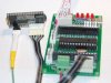
I've decided to build a small circuit that will integrates
- ICSP (with its capacitor, resistor and diode)
- 16/2 LCD (with its back light resistor, r/w jumper, contrast pot)
- Serial connector (with its resistor)

All will be plugged in via a straight header on the breadboard. I will use Pickit2 to provide power.

Any thing else I should integrate?

Mike
 
7 segment I would not use, I normally display all required info on the LCD.
I would normally use ADC from an external source.
buzzer/piezo, good idea.

How would I implement serial over USB?
Or do you mean for PICs with integrated USB?

Mike
 
You might look at my TAP-28 board. I designed it for similar reasons but with a little different philosophy. Most of what I do involves hooking up some small amount of stuff to a PIC, such as a sensor or a breakout board using I2C or UART coms. I designed the board to be cheap, without a lot of extra features so it could be dedicated to a project and with connectors for the things I'm likely to connect. What I've ended up with is this:

  • 3 6-pin connectors, 1 for ICSP, 1 for UART and 1 for I2C/SPI. Each has 4 port pins, power and ground. They can be used for the hardware function or as general -purpose port pins.
  • 4 3-pin connectors, 2 with ADC inputs, 2 with PWM outputs. Each has power and ground in addition to 1 port pin.
  • 2 parallel SIP connectors with all the port pins, power and ground so a daughterboard can be added for additional functions. An example is a daughterboard with a UART-USB adapter for serial coms to a PC...which is someplace between here and China at the moment.
  • The board also has 4 LEDs and 2 pushbutton switches for general purpose use.

The result is a flexible board that's cheap enough to embed in a project without worrying about the cost. It works really well for stuff like this as connectors are used for interfacing to any external parts instead of a rats next of jumpers.

The picture below shows the TAP-28 board connected to a thermocouple circuit I'm working on which is interface via I2C.

http://www.clever4hire.com/throwawaypic/


Jon
 

Attachments

  • tc brd + TAP-28.jpg
    tc brd + TAP-28.jpg
    104.9 KB · Views: 185
Last edited by a moderator:
Hi Jon,
This is a great product but I think it would be over-killing for my needs, I work with many PICs and I need just the basic stuff, so far I got LCD, ICSP, Serial, and piezo. Switches I would not integrate because they are quick to plug in and I have made some small PCB that includes leds+resistor and I just plug them in the breadboard.

But if my field of interest changes I know where to go, thanks for the info.

Mike
 
Thanks Mike,

I designed the TAP-28 because I was either spending a lot of time soldering up a circuit on perfboard or using more expensive dev boards for applications where I wanted a simple PIC circuit. Building a perf board always takes longer than it seems like it should (especially if there's a short or something ends up in the wrong place!) and dev boards have a lot of features I don't use and not the ones I need.

The plug-in board sounds like a great idea. Are you going to bring all the port pins out to a row of header pins? Should be handy.
 
I will use Pickit2 to provide power.

Hi,

As you can see a development board does just that - it develops as your needs change.

I've made a few over the years, ealry ones on strip board etc.
My latest offering has all the standard stuff light lcd, switches,leds, regulators etc on on board and individual project boards, be they pcbs, strip board or bread boards, simply plug into that.

One problem with your design is the Pk2 will only pass about 25ma to the target circuit so you want to avoid blowing the Pk2 at all costs.
Either bring the USB +5v onto your board via extra usb sockets etc or if you do not mind hacking the Pk2, you can disconnect its pin 6 and wire that to the +5v on its usb socket so you have a direct usb +5v feed.
 
I never use devboards or perfboards, I normally build on breadboard and when the circuit is good I make a PCB. LCD Display is normally only for troubleshooting and seeing what's going on in the PIC and when there is too much data I use a serial connection. I have an old Thinkpad with serial. If I find a simple circuit to convert serial to USB I might just do that. My goal is to get going faster with all the tools I need and also to make the breadboard cleaner. As I am still in the design I've decided to discard the piezo since it is not really an issue to insert 2 wires in the board. So far my board will have a 12 pins header and this will same me lots of time.


I would recommend an expansion header so you can add things later.

Wilksey

I am not sure how I would implement this, do you have any suggestions?

Mike
 
Hi,


One problem with your design is the Pk2 will only pass about 25ma to the target circuit so you want to avoid blowing the Pk2 at all costs.
Either bring the USB +5v onto your board via extra usb sockets etc or if you do not mind hacking the Pk2, you can disconnect its pin 6 and wire that to the +5v on its usb socket so you have a direct usb +5v feed.
I actually never looked up to see how much current the Pickit2 can support, 24ma is very little I guess I've been lucky. So I will just add an external power and plug in a USB cable.
Thanks for the suggestion.

Mike
 
Last edited:
Piece of cake if you are developing a PCB!

Just have a 20 / 40 way IDC or SIL connector on your board and route all unused pins to the IDC or SIL, that way if you decide you need to connect something else you can just plug into the expansion header, very useful for surface mount PIC's!

If you are using a breadboard you may just want to break out some more useful pins like TX/RX, I2C, SPI etc as the wiring on a breadboard will be hectic!

Wilksey
 
No probs.

There will always be something you want to connect, but never in a million years would you think of it when making a dev board, that way when the inevitable happens you will be prepared!!

Wilksey
 
I believe the PICkit 2 will actually supply about 100 mA.

One brainstorm I had a while back was using a software UART with the PCIkit 2 to monitor program output. Setup the software output to use the appropriate port pin on the ICSP connector. Then it's a simple matter to load code, then switch to the PICkit UART tool. No need to change connectors or have additional hardware.
 
Last edited by a moderator:
Status
Not open for further replies.

Latest threads

New Articles From Microcontroller Tips

Back
Top