Electro Tech is an online community (with over 170,000 members) who enjoy talking about and building electronic circuits, projects and gadgets. To participate you need to register. Registration is free. Click here to register now.
Welcome to our site! Electro Tech is an online community (with over 170,000 members) who enjoy talking about and building electronic circuits, projects and gadgets. To participate you need to register. Registration is free. Click here to register now.
I don't think that a zero cross opto-isolator would be the preferred option. You will want to detect a difference in potential.
If there is a blown bulb, the sense line is connected to the neutral through a high impedance. There will be no voltage present.
so compared to N, there would be NO VOLTAGE present... and when there is a bulb connected, there would be what there? 240v AC... and thru an opto isolater, what wouyld i get
It doesn't matter whether it switches the live of neutral. Normally the former is mandated for safety reasons but a triac isn't suitable as a safety critical power switch for the prevention of electric shock because there's a risk it might go closed.
The idea is you power the LED in an transistor opto-isolator using a standard mains powered LED circuit.
so your sayin instead of turning on the LED on the output, i put this to an input of my PIC... so when theres 240vAC then ill get a logic 1... and if its not 240v i get zero meaning i can sense if there is a bulb there or not?
the opto isolater circuit u showed, thats what i need????
Now I don't understand what you're saying. Please try and use better English.
If the triac is off and the bulb it present the opto-isolator will turn on other wise it'll be off. Obviously this operation will be reversed if the transistor on the opto-isolator is pulling down a pin on your pic connected by a pullup.
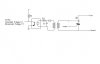
On closer examination of the resistor requirements needed to couple 240Vac to the input of an opto isolator, I believe it would be wise to use a small step down transformer in conjunction with the opto isolator. See attached.
that circuit makes sense, but if i have 8 channel outputs... then your sayin i need 8 small transofrmers... seems a bit of an in-efficient way to do it?
what would these "small" transformers look like - i bet there heavy aswell..
I didn't realize that you were attempting to monitor 8 circuits.
So in what areas are you able to compromise.. cost, power efficiency, size/weight, ease of construction, etc ?
What is the wattage of the 8 bulbs?
How soon must a blown bulb be reported?
For the purpose of detecting a blown bulb, is shutting off or turning on all bulbs acceptable?
How much flexibility/control do you have with regard to modifying the control software used in this application?
How many PIC output/input lines do you have available?
The type of transformer I was referring too, is a small Hammond transformer that is about 1.25 cubic inches and weighs about 0.2 lbs.
If an additional 1.5 lbs is too much, then it is back to the drawing board.
Direct coupling of 240 volts to an opto isolator requires about a 3 watt resistor.
yes i have 2 PHYSICALY BOXES... each with four bulbs connected to it..
possible bulbs are between 60W to maybe 500W... or a MAX of 1000W between FOUR
It will be plug powered (the whole box)
cost is a factor id like to keep down, i already have a 240V -> 9v transformer, which is a bit weighty...adding extra weight is not a big issue.
i just wanted a circuit that i could sense when there was an OPEN circuit on the LIVE line...i.e BULB
When a CH is open ciruit, id like it to set a BIT in a register and when i command from my PC application to "get" diagnostics, it sends this byte back so i can decipher what is OK and what is BAD... BUT in the end id like to have diagnostics sent periodically so i know when a bulb is O/C
if all i need is a couple of 3w resistors and a opto-isolater id be happy..
i just want 5V going to an input if there IS GOOD CONNECTION and 0V to the input if BAD CONNECTION.
Can that be possible with the 2 resistors and isolater on the live side?
it seems similar to my ZERO CROSS DETECT ISOLATER circuit, except thats HIGH for 10ms and LOW for 10ms, when i just want it HIGH ALL the time if i have a GOOD connection?
turning off all bulbs or turning on all bulbs is acceptable... not ideal, i guess i could POLL four inputs as my program is interrupt based, that shouldnt be a problem, or i could use the top 4 bits of port b and use the special function interrupt to report a blown bulb
and automatically send that back2 the PC...but that i can do easily, its just the electronic side of it...
its so i can do interesting things such as "ACCOMODATE" the blown bulb by increasing the intensity on close bulbs so it doesnt effect it
ok ok ok ill shhh about where i want to head... if u could add a circuit of what could work so i can visual is...if not, word explanation is next best thing
This site uses cookies to help personalise content, tailor your experience and to keep you logged in if you register.
By continuing to use this site, you are consenting to our use of cookies.