Continue to Site

Welcome to our site!

Electro Tech is an online community (with over 170,000 members) who enjoy talking about and building electronic circuits, projects and gadgets. To participate you need to register. Registration is free. Click here to register now.

  • Welcome to our site! Electro Tech is an online community (with over 170,000 members) who enjoy talking about and building electronic circuits, projects and gadgets. To participate you need to register. Registration is free. Click here to register now.

DESPERATE TIME DESPERATE MEASURES WITH MY POWER SUPPLY!

Status
Not open for further replies.
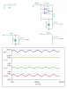
Stage two is the precision voltage reference, for lack of a better term. ... and it ends at the wiper arm of the potentiometers.

The other two op amps close the loop to keep the output set at the specific value and are part of stage three.

Does your "book" cover have some identifying information?

It's best to handle this via the forum, so someone in the future can learn ...
 
Getting back to the OPs problem:
i have finished stage 1, now one to stage 2, installing the chips and such, for some reason..my chips arent giving me the right voltage..When i turn the pot one way im getting around 16 which is int he ballpark but when i turn it the other way it stays on 16v.

JoeJester touched on this earlier when he asked:
where did you connect R22 and R9 ... the other end away from the negative input terminal of the OP AMPS ?
What you have when R22 and R9 are not connected are op-amps with no feedback.
The behaviour you describe where the output goes high or low and cannot be set in between is typical of such a situation.
To help you with your staged testing, I suggest that you connect the free ends of those resistors to the output pin of their respective op-amps.
The op-amp output voltage should then change as the voltage control pot is adjusted.

JimB
 
Earlier I commented:
What are the op-amps doing which feed the voltage adjustment pots?

JoeJester made the comment:
Stage two is the precision voltage reference, for lack of a better term.

I am not sure if this comment was directed to me, but I do understand the purpose of "stage two", what has me scratching my head is the op-amps wrapped around the zener diode.
At a first glance, it appears that the diode is just being driven by the output of the op-amp. Why?
Looking again, I thought that it may be a means of providing a constant current drive to the zener. If it is that, I am not seeing how it is supposed to work.
I dont think that I have ever seen a configuration like that before.

JimB
 
As I understand stage 2, the opamp + zener + voltage divider at the op-amp input behave in a similar way to an 'amplified diode'. If the divider ratio is n, then the opamp output will be n x zener voltage and will also be a relatively constant voltage drive for the zener.
Edit: That said, I don't think the end result would be much more accurate than simply driving the zener from the main power supply via a resistor.
 
Last edited:
alec_t
That makes sense, or at least it would in this case if the output from the voltage reference circuit was taken from the output of the op-amp, rather than from the junction of the zener and its series dropper resistor.

JimB
 
I agree Jim.
Out of interest, here's a simulation comparing the zener voltage obtained by using the stage 2 arrangement and the simple single-resistor drive arrangement I mentioned. The resistor is sized to give ~ the same zener current in both arrangements. The plot shows zener voltage where Vin goes from 25 to 40V (x-axis) and temperature is stepped from -20 to +40. I rest my case :).
ZenerDriveComparison.gif
 

Attachments

  • ZenerDrive Comparison.asc
    2.5 KB · Views: 270
Stage two ...

I agree the op amp, zener diode, and voltage divider looks unusual. I did a comparison of three simple voltage references. For exaggeration purposes, I had the 20V supply exhibit a 2 Volt pk-pk 60 Hz sawtooth (ripple). The reason for the circuit is clear.
 

Attachments

  • Voltage-References.png
    Voltage-References.png
    17.1 KB · Views: 287
Very good point Joe.

This is relying on the power supply rejection of the op-amp, and giving a very useful improvement in circuit performance.

I have learned things here in this thread.

JimB
 
Joe, try matching the zener currents in your scenarios (e.g. reduce R2 to ~3.3k). I think you'll find that V1ref and V2ref are then better matched over the input voltage range. I'm seeing only ~5mV ripple on V2ref (which admittedly is absent in V1ref). The ripple reduces to 2.8mV if the supply voltage is derived via the Stage 1 stabiliser.
 
Alec,

I see what you mean. I only used the high ripple in the example to show an extreme as I was curious on why that topology was used.

That feedback scheme serves a useful purpose in stage three as well. Looks like it could be a very stable, precision, power supply.

All the negative comments about it being a half-wave rectifier appears to have been resolved.

Jim,

I too learned something from this thread.
 
Last edited:
I too learned something from this thread.
Me too. That's the good thing about forums. We're none of us too old to learn (though remembering what one has learned gets more difficult with age :)).
 
Status
Not open for further replies.

Latest threads

New Articles From Microcontroller Tips

Back
Top