Continue to Site

Welcome to our site!

Electro Tech is an online community (with over 170,000 members) who enjoy talking about and building electronic circuits, projects and gadgets. To participate you need to register. Registration is free. Click here to register now.

  • Welcome to our site! Electro Tech is an online community (with over 170,000 members) who enjoy talking about and building electronic circuits, projects and gadgets. To participate you need to register. Registration is free. Click here to register now.

Design for $$??

Status
Not open for further replies.

daviswe

New Member
I'm an EE, but a bit rusty. I want to make a 600-Ohm dynamic mic work with my Harley Davidson intercom system in my Ultra Classic, for a roll-your-own headset. I have the speakers all worked out, now for the microphone, which runs into a VOX circuit, so there's a thresholding section somewhere in the HD radio. FWIW, I have tried using dynamic mics and condenser mics (there's 8VDC on the mic lines) but they do not trigger the VOX, so I'm assuming the preamp is required (below) to get to the radio's threshold level before they will break VOX. HD headsets are known for horrible performance, so I'm trying to do a better mic. I don't mind using a condenser mic, almost would prefer it for size. I have a great sounding dynamic I use on my Goldwing and other systems, I could use that too.

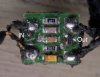
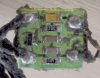
The Harley headsets have a 200-Ohm dynamic mic running into what appears to be a small surface-mount board (see attached, component side and traces visible images) which is probably a mic preamp. I'm going to run it this afternoon with my Dual Trace scope on the input and output and see what the board is doing and I'll report later. I am pretty sure it's just a small single transistor amp, but I don't know what all the parts are in the image. The 105C No3 1C thing is one I can't identify. Looks like a diode, 2N4401 equivalent on the output side, couple resistors 100k and 2K, and two UFO's, probably lavendar and brown capacitors of unknown values...

What I'm looking for is to buy a design from someone willing to take it on, reverse engineer it or help me come up with a better design. I could probably do this given time, but reverse engineering the SMT board is not easy since some components are not labeled and I want a quality design, which HD does NOT provide :)

Details to follow...I'm going to determine whatever gain and wave shaping it does today, that's probably all I can do.

Ed
 

Attachments

  • HDPreamp.jpg
    HDPreamp.jpg
    61.3 KB · Views: 197
  • HDPreamp_Traces.jpg
    HDPreamp_Traces.jpg
    68.9 KB · Views: 194
Last edited:
It looks like it's just a filter, probably for impedance matching. There are no power leads going to it (that I could see) so I doubt there is any amplification.

The 105C is a capacitor.
 
Last edited:
As I mentioned in the original post, there is 8VDC on the mic lines on the 'output' side, which provides both bias and power to the transistor.
 
Yea, not really good at identifying SM stuff yet. :)

Or reading thoroughly, as well. :p
 
The circuit looks like an electret mic pre-amplifier.

Audioguru is the right man for you. :)

Boncuk
 
I can't find a way directly contact Audioguru, but if anyone can point me to him, or him to me, I'd appreciate it.

Ed
 
Why do you want to contact him directly?

If it's to ask an electronics related question then I'm sure he'd rather you ask on the open forum and direct the question at everyone not just him.
 
Are all of the traces shown in the back-lit picture on the component side of the board?

Is there any chance you could use a continuity tester to confirm the connections that we can't see and pencil them into one of the photos? I have built similar modules and this one looks simple. If you tell us what it does poorly we might find it easy to improve.
 
I don't need to contact him privately, I just don't know whether he will see this post, and really there's no way to 'ping' someone or invite them to a thread.

I have not finished my testing, but hope to do it this weekend. I biased it up and sent a 1K tone via speaker into the mic, but was not able to see signal at the output side, so I probably need to put a load resistor on it (not attached to the main amp) and then I can have a drop to look at with the other channel of the scope. the mic is generating about a 5mV ac.

I will also verify the traces, and if possible, snap scope images of the signal at various points. I can't disassemble it farther since it does need to go back to its owner :)

Ed
 
Last edited:
Sorry, I was busy today.
The "preamp" might be a circuit to simulate a horrible old carbon microphone.
The transistor amplifies the electret microphone then modulates the supply current.
I don't have any circuits for that old poor quality stuff.
 
Actually, the circuit is amplifying a DYNAMIC mic, 200-Ohm, which produces about 5mV signal on its own. I'm setting up the scope this morning and will be running the gain tests and such today. My working theory is that they are bumping it up to line level or something more than a typical mic level signal to reduce noise, but I'll know more later this afternoon.

Thanks for responding.

BTW, I do have a 'Carbon Mic' simulator curcuit someone else posted on another board if you're interested...

Ed
 
Ok, I finally got some specs. The little ckt has a voltage gain of about 90dB, meaning a 20x jump from a 5mV mic signal to 100mV preamp out signal level. It drives a 1KOhm input impedance (measured by inserting a 1K resistor inline and during use, measuring a 5Khz signal on both sides of the resistor, calculating impedance from the current and the amp side voltage on the resistor).

I built a 741 Op-Amp ckt to check this and it seems to work ok to trigger the vox on the intercom system. So the trick now I suppose, is to miniaturize my circuit.

Back to the original question, can anyone do this design for a fee?

Ed
 
90dB is a voltage gain of 32 thousand, not 20.
26dB is a voltage gain of 20.
 
Yeah, I noticed that too. I have no clue what I was thinking. Never pays to write quickly while doing other things as well. 32K voltage gain would probably trigger the vox, for sure!

Ed
 
No, it was potted with silicon and I had to carefully pinch it off with tweezers. The wires are actually enamel coated, hence no real jacket to speak of, just the residual silicon.
 
Status
Not open for further replies.

New Articles From Microcontroller Tips

Back
Top