Continue to Site

Welcome to our site!

Electro Tech is an online community (with over 170,000 members) who enjoy talking about and building electronic circuits, projects and gadgets. To participate you need to register. Registration is free. Click here to register now.

  • Welcome to our site! Electro Tech is an online community (with over 170,000 members) who enjoy talking about and building electronic circuits, projects and gadgets. To participate you need to register. Registration is free. Click here to register now.

Depolarising electrolytic capacitors

Status
Not open for further replies.

alec_t

Well-Known Member
Most Helpful Member
For AC coupling, polarised electrolytic capacitors are less than ideal but sometimes have to be used in a situation where they are subject to reversing polarity. The accepted way is to use two in series, back-to-back. This is supposed to prevent their depolarisation. But how does that work? Both caps will be subject to reversing polarity, so what advantage is there over using a single cap?
 
alec_t,

For AC coupling, polarised electrolytic capacitors are less than ideal but sometimes have to be used in a situation where they are subject to reversing polarity. The accepted way is to use two in series, back-to-back. This is supposed to prevent their depolarisation. But how does that work? Both caps will be subject to reversing polarity, so what advantage is there over using a single cap?

You should certainly work to find a unpolarized electrolytic. They do exist, especially for motors. If you cannot find one, then perhaps a diode in parallel across each cap so as to not let the reverse voltage exceed more that 0.7 volts or so.

Ratch
 
IIRC, there is a sort of oxide layer on one plate to provide higher capacitance via reduced thickness in the dielectric while simultaneously preventing leakage in one direction, kind of like a reverse biased diode. Reversing the voltage on a polarized electrolytic results in additional leakage, heating, and eventual degradation of the dielectric. Placing the capacitors back to back prevents leakage in both directions but is less than ideal. A bipolar electrolytic will work better.

Try it sometime. Put a filter cap in backwards after a bridge rectifier. It works fine, for a while. We had a vendor get this wrong on a regular basis with 35V caps on rectified 16VAC. Unless we were 100% sorting, we couldn't detect it until it failed in the field weeks or months later. They did the same thing with some tantalums too. They generally failed much quicker, sometimes after mere minutes, generally within a few hours.
 
For AC coupling, polarised electrolytic capacitors are less than ideal but sometimes have to be used in a situation where they are subject to reversing polarity. The accepted way is to use two in series, back-to-back. This is supposed to prevent their depolarisation. But how does that work? Both caps will be subject to reversing polarity, so what advantage is there over using a single cap?
That's how the non polar caps are built (two caps end to end)
 
Last edited:
alec_t no there is no reverse voltage occurring, the two ends of the capacitor connected to each other are floating from the rest of the electrical world so no reverse voltage is ever applied, it doesn't really make sense to me either at quick glance but it works. Leakage current might induce some non zero voltage though but probably not enough to bother anything unless one or the other of the two caps starts to fail.
 
@Ratchit
Thanks. I don't actually want to build this; it's a theoretical conundrum.
@bountyhunter
Again, thanks. I was aware of that.
@Sceadwian
If I put, say, 1V across back-to-back caps that voltage will be divided between them somehow. One or other must be reverse polarised. With an AC signal a small charge/discharge current will flow (not just leakage current).
 
For AC coupling, polarised electrolytic capacitors are less than ideal but sometimes have to be used in a situation where they are subject to reversing polarity. The accepted way is to use two in series, back-to-back. This is supposed to prevent their depolarisation. But how does that work? Both caps will be subject to reversing polarity, so what advantage is there over using a single cap?

An electro cap acts very similar to a short circuit when reverse connected. Basically one cap is acting like a diode (turned on) because it is reversed compared to the voltage. So two polarised caps in series (one reversed) works well as a non-polarised electro cap.
 
Last edited:
Thanks all. Looks like there's two camps. I'm in the "don't think it's a good idea" one, but I assume that back-to-back caps of, say, 50V rating are unlikely to be troubled too much by ~1V AC across them.
 
I had an old, expereinced analog engineer who said it would be OK but use only as a last resort. He also said to make sure each capacitor is connected to a DC voltage at it's rated voltage before connecting together.
 
Last edited:
I dont know all the pro's and con's about Electrolytics back to back to make a non-polar...all I know is that it works on Chinese TV East-West stages:

CRT sets only.

These sets normally have a fat non-polarised 10mF rated at around 50V that tends to dry out and cause East-West problems (picture bows in from the sides).

I use two 22mF 100V caps with the negatives soldered together in place of the non-polar. No problems in that specific application.

Cheers,
TV Tech
 
Last edited:
For the vast majority of hobbyist activities back to back electrolytics work just fine.

In a manufacturing environment, two capacitors instead of one means more board space and more money.

Given the secretive nature of electrolyte formulas and other materials, I would assume actual bipolars have probably been optimized for such applications and would outperform back to back polarized caps in a rigorous testing environment where ESR, ESL, leakage, stability, temperature coefficients, and all the rest are being quantified and tracked.

OTOH, the number of projects I've been involved with where such subtle performance differences really mattered: zero.

It used to be my job to do this to electrolytic capacitors with rectified 120VAC. The 2500µF 200V ones went in less than an hour and tripped the circuit breaker where he's probably continuing to pump 50 or more Amps through it at a lower voltage. I wish I knew the voltage rating of that capacitor. I stopped the test after about 45 minutes and went home before the 400V ones blew. The project was then discontinued before I got around to repeating the test with 400V capacitors.

Big Capacitor Vents With Flames And Explodes
 
I think there are some problems with that article. Look at this article. It's an app note from a capacitor manufacturer. It states:

If two, same-value, aluminum electrolytic capacitors
are connected in series, back-to-back with the positive
terminals or the negative terminals connected, the
resulting single capacitor is a non-polar capacitor with
half the capacitance. The two capacitors rectify the
applied voltage and act as if they had been bypassed
by diodes. When voltage is applied, the correct-polarity
capacitor gets the full voltage. In non-polar aluminum
electrolytic capacitors and motor-start aluminum
electrolytic capacitors a second anode foil substitutes
for the cathode foil to achieve a non-polar
capacitor in a single case.

Also, see the model on page 2.187. It shows how the reversed capacitor gets bypassed in a back-to-back connection. I always had my doubts about using this method, but after reading this app note, I finally understand why it works.
 
Last edited:
Brownout- I already explained it in post 7. The reversed cap acts like a short so for each polarity of the waveform only the correctly oriented cap works like a cap.

It's perfectly safe from my experience. In the old valve (tube) amp days even some of the manufacturers used 2 back to back electros to make HV non-polarised caps when there was no suitable uF or voltage rated non-polarised cap commonly available. I had also replaced non-polarised HV caps with back to back electros to get valve amps working for gigging musicians, and those amps lasted the distance, years of hard use.
 
Last edited:
The two capacitors rectify the applied voltage and act as if they had been bypassed by diodes.
I'm not convinced about rectifying the applied voltage, but clearly if a cap is reverse-polarised it acts as though it is by-passed by a forward-biassed diode, limiting the voltage across it. Provided the current through it in that state is limited to a level which doesn't cause excessive internal heating it is obviously ok. Presumably any destruction of the oxide layer electrochemically during one half cycle is balanced by oxide build-up during the next half cycle.
 
I'm not convinced about rectifying the applied voltage

Here's a simple experiment that might convince you. Take the model for the capacitor form the link, replace one of the back-to-back capacitors with a resistive load, and then simulate it in LTSpice. I'll bet you get a rectified voltage from it.
 
Last edited:
I'm afraid you've lost your bet :D
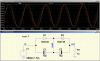
. I did a sim as you said, with one of the caps replaced by a resistor. I also did a sim with back-to-back caps. The results were similar: no sign of rectification in either sim.
 

Attachments

  • BackToBackCaps.png
    BackToBackCaps.png
    21.3 KB · Views: 305
Not so fast. You won't see it in the back-to-back case, because each device rectifies different polarities, resulting in a re-constructed wave. Also, are C1 & C2 electrolytic models? And if so, are the diodes oriented correctly? I'll try a sim myslef at home. Can't do it right now.

Ps: I had to re-read the app note. I think it's saying the rectified voltage would show up across the cap. So, instead of connecting the resistive load in series, connect it in parallel. The rectification should reveal itself.
 
Last edited:
Status
Not open for further replies.

Latest threads

Back
Top