Continue to Site

Welcome to our site!

Electro Tech is an online community (with over 170,000 members) who enjoy talking about and building electronic circuits, projects and gadgets. To participate you need to register. Registration is free. Click here to register now.

  • Welcome to our site! Electro Tech is an online community (with over 170,000 members) who enjoy talking about and building electronic circuits, projects and gadgets. To participate you need to register. Registration is free. Click here to register now.

Dead Spot

Status
Not open for further replies.

ricker24

New Member
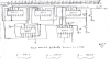
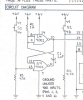
I am putting together a 25 Led counter with push button switch. I have cascaded 3 4017 CMOS together the way the datasheets show. I am getting a good count until I get to 17. It counts straight through to 17 with one button push each time until I get to 17 and then I have to push 2 times to get led 18 to light and then the rest count normal. I am new to this site and fairly new to electronics but I am sure I have everything correct as far as parts and wiring. Can someone tell me if this is normal or if there could be a fix for this. I am attaching a rough drawing of what I have and I mean rough. Any help will be greatly appreciated.
 

Attachments

  • 25 led counter.pdf
    186.5 KB · Views: 168
I was unable to open your file, but it sounds like what you have going on is a reset pin is connected to one of the output pins so it is skipping that number. Can you post the schematic as an image file, and we will be able to help you more.
 
Hi ricker24,

you might want to try that circuit. Current limiting resistors omitted. (For demo only!)

Boncuk
 

Attachments

  • 25-LEDS.gif
    25-LEDS.gif
    14.4 KB · Views: 203
I hope this works...
Since your supply is only 6V then the typical output current of a CD4017 into a short circuit is only 7mA. Into a 2V red LED without any current-limiting resistors the current is 5mA which is dim. The current is low and only one output is high at a time so the IC will not even get slightly warm.

You have pin 3 output of the left CD4017 trying to blink an LED plus clock the next CD4017. It cannot do both.

You have a 1uf power-up reset capacitor shown with backwards polarity.

You have a pushbutton as the clock without a de-bounce circuit (its contacts bounce many times each time it is pushed and the counters will count all the bounces).

You have the pin 11 of the CD4001 floating.

You have all CD4017 ICs without 0V on their pin 8.
 

Attachments

  • CD4017 output current.PNG
    CD4017 output current.PNG
    28.2 KB · Views: 167
Last edited:
If he wants to see it bigger all he has to do is "Press and hold Control Key on the Keyboard" the with his mouse and use scroll.

If he's in Explorer or FireFox goto view and go down to Zoom in or Zoom out.
 
As far as pin 3 on the data sheet for the 4017 this is the way it shows it. It shows pin 3 as a cascade point and also an output so that is what I was going by. I am using the 4001 as the debounce and it seems to work fine as far as a clean count and the schema that I used for it is from one of my electronic books and it shows the capacitor + to pin 11 and - to pin 8 and 9 with them going to + with resistor.(Is this incorrect in my book?) For the pin 8 on the 4017's that is my fault because I have them grounded but forgot to show that on my rough drawing. Thanks for your reply...
 
You are using NAND gates (CD4011) but the datasheet uses AND gates (CD4081) which might be causing your "dead spot".

Your 1uF capacitor polarity and your book are wrong. The + wire of the capacitor should be at pins 8 and 9 that are almost always at +6V by the resistor. The - wire of the capacitor should be at pin 11 where it is driven to ground.
 
Thank you. I will try the 4081. I guess I was using the 4011 because of another schema that I found 1st for cascading the 4017's and did not even notice that it was using the wrong gate according to the data sheet. I will flip the capacitor too. Thanks again and I will let you know what happens with the changes. Thank Again...
 
Thanks so much for all of your help. I switched the 4011 gate for a 4081 gate and it works perfect now. I missed that completely because the 1st schema I found for cascading the 4017 showed a 4011 and I guess I just had that in my head and did not catch it on the true data sheet. As far as the capacitor it seems to work either way but I have put it the way you said to put it. Thanks again so much for all of your help.


You are using NAND gates (CD4011) but the datasheet uses AND gates (CD4081) which might be causing your "dead spot".

Your 1uF capacitor polarity and your book are wrong. The + wire of the capacitor should be at pins 8 and 9 that are almost always at +6V by the resistor. The - wire of the capacitor should be at pin 11 where it is driven to ground.
 
To make sure that I am not looking at something wrong this is the part of the schema that is in my projects book on the capacitor polarity. I had it connected this way 1st and it didn't seem to matter when I switched it.(Why would this be and will it cause damage connected backwards?) I thought it was kind of strange to start with but am fairly new to electronics and just went by the schema.Thanks...


You are using NAND gates (CD4011) but the datasheet uses AND gates (CD4081) which might be causing your "dead spot".

Your 1uF capacitor polarity and your book are wrong. The + wire of the capacitor should be at pins 8 and 9 that are almost always at +6V by the resistor. The - wire of the capacitor should be at pin 11 where it is driven to ground.
 

Attachments

  • capacitor.PNG
    capacitor.PNG
    184.3 KB · Views: 144
Yes the capacitor has backwards polarity when the pushbutton is pressed. It might cause the circuit to malfuction. If the button is pressed for a long time then the capacitor will "deform" then fail.
 
Status
Not open for further replies.

Latest threads

Back
Top