SneaKSz
Member
Hello guys,
long time ago!
I was looking at the types of armature winding of a DC motor and something confused.
Link: **broken link removed**
Page 1-29 and 1-30.
I added the pictures in the attachment.
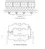
Someone has an idea why the connection of the conductors of the development diagram and the image below doesn't match?
e.g. commutator segment 4 goes to conductor 7 and 12 at the fig 1.27 while
for fig 1.28 it goes to 6 and 12.
Commutator segment 1 goes to conductor 1 and 6 at the fig 1.27 while for fig 1.28 it goes to 1 and 7.
I assume the fig 1.27 and fig 1.28 are related to each other in terms of connections of the conductors and commutator segments.
Thanks a lot in advance guys.
Happy NYE!
long time ago!
I was looking at the types of armature winding of a DC motor and something confused.
Link: **broken link removed**
Page 1-29 and 1-30.
I added the pictures in the attachment.
Someone has an idea why the connection of the conductors of the development diagram and the image below doesn't match?
e.g. commutator segment 4 goes to conductor 7 and 12 at the fig 1.27 while
for fig 1.28 it goes to 6 and 12.
Commutator segment 1 goes to conductor 1 and 6 at the fig 1.27 while for fig 1.28 it goes to 1 and 7.
I assume the fig 1.27 and fig 1.28 are related to each other in terms of connections of the conductors and commutator segments.
Thanks a lot in advance guys.
Happy NYE!