Continue to Site

Welcome to our site!

Electro Tech is an online community (with over 170,000 members) who enjoy talking about and building electronic circuits, projects and gadgets. To participate you need to register. Registration is free. Click here to register now.

  • Welcome to our site! Electro Tech is an online community (with over 170,000 members) who enjoy talking about and building electronic circuits, projects and gadgets. To participate you need to register. Registration is free. Click here to register now.

dc electric motor question

Status
Not open for further replies.

adeyo

New Member
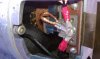
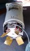
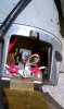
i recently picked up a 1 HP dc electric motor from a salvage yard, and i was planning on following a guide to convert my gas mower to electric. The only problem is, there is no posted schematic on my motor and the 4 wires coming out seem to be very thin gauge! no rpm posted, no voltage posted, only HP... my questions are:

1) is there a way to figure out the voltage?
2) what is the 4th blue wire for???

The motor is probably mid to late 1980's and about 5" diameter by 10" height.

My needs are a high voltage, low amp drawing motor to spin the mower blade. I just need to be able to figure out what type of batteries i can hook it up too w/o frying those wires! (6Volt, 12V...24V???) how can i figure this out?

Thanks for any tips...my first post :)
 
if it is 24V it will consume around 30A, but if it is 110, it takes around 6A and around 3A for 240.
 
Well if you have a known DC motor with 4 wires exiting I would venture a guess that two wires are Armature and two wires are Field. Sometimes labeled A1 & A2 and F1 & F2. You can start by looking at the resistance between any two pairs. Therefore a good start would be to figure out which wires do what.

Ron
 
It might also be a good idea to find out from what it was salvaged.

Boncuk
 
wow, all those comments are so helpful!! Thanks everyone. I guess my follow up question would be the following...

Question #2:

**what is the best way to proceed (i.e. "experiment") with getting this motor running on some sort of dc battery (a deep cycle with a large capacity would be best), without frying the wires of course??? High Voltage, Low amperage is best for what i want to accomplish, but i obviously need to pull high voltage off with batteries to keep amperage low and so i can mow without a cord attached...any tips on the best battery setup to try??

btw, here is the basic schematic I plan on using...although, i don't know what changes to make with my thin gauge wires (afraid of frying them/the motor) ... http://www.arttec.net/Solar_Mower/4_Electrical/Mower_Schematic.jpg
 
Last edited:
OK if you go back and read what collin55 wrote about thin wires.

If it has thin wires and is 750watt motor, the voltage will be 110v to 240v

We know it is a 1 HP motor. So 1 HP = 746 Watts but actually more since this is not an ideal world. The thin wires would lead a person to believe this is around a 120 volt or 240 volt DC motor. However, you have 4 wires exiting the motor. That leads me to believe this was likely a variable speed DC motor with seperate field and armature windings. You are going to have to check the resistance of those leads and see which goes where. With luck you will have two pairs with resistance between them. Do you know what country the motor originated in? We are sort of working in the dark here.

Do you see brushes in the motor? Maybe a strap cover offering access to brushes?

Ron
 
Last edited:
Thanks Ron...here are 3 pics...the tag on the outside says "PSI - Peripheral Support ...a division of MESON Corp" ...i think it is made in the USA...for military. What is your take from the pics? Do i need to post more/different ones?? Also, how exactly do i test the resistance of those leads? I access to whatever meter(s) i need...just let me know what type. Thanks for helping out a noob :)

Thanks!!!

**EDIT: btw, if it is variable speed w/ seperate field and armature windings, and if it is a high voltage motor (120/240 etc.) that means i am out of luck trying to use it for my application right? (i can't use a 24V or 12V deep cycle marine battery then?)
 

Attachments

  • IMAG0048.jpg
    IMAG0048.jpg
    1.2 MB · Views: 470
  • IMAG0057.jpg
    IMAG0057.jpg
    1.5 MB · Views: 439
  • IMAG0052.jpg
    IMAG0052.jpg
    1.5 MB · Views: 344
Last edited:
Good pictures and I can tell you the following. The top number on the nameplate is a NSN (National Stock Number) and you were on target in that it is a piece of military surplus and unless another country uses NSN I would say US military. The bottom number, Contract Number is the contract number the part was made under for the US Govt. The NSN denotes a federal part number which likely had several manufacturers for that same motor and the Contract Number links it to the company whose name you see on the name plate. I couldn't make out the full NSN but maybe with a Google something will turn up?

The motor itself is a brush type DC motor as the brush springs are quite visible and it has 4 brushes. The brushes ride on the commutator of the armature. Likely one wire will go to two brushes and another wire to the remaining two brushes. The brushes with common wires will oppose by 180 degrees if I guess right. The brushes are carbon in the brush holders with spring loading pushing them down on the commutator. I can't see how much wear they have but the commutator looks OK.

So what you need is an ohmmeter to do a few resistance checks. One wire will go to one set of brushes and another wire will go to the other set of brushes. Those two wires will be the A+ and A- I mentioned earlier. They will be a pair.

The remaining pair should show a resistance between them. Those will be the field windings which the armature rotates inside of. There should be no resistance (continuity) between the field winding and the brush leads.

The motor is a variable speed DC motor. Now I may have this backwards but with motors like this (1 HP) I think they use a fixed voltage on the commutator and vary the voltage to the field windings. That may be backwards as I said. I can tell you that using a motor like this for your intended use won't be very easy or practical. :(

<EDIT> On second glance the brushes and commutator look real good and I see one field wire (maybe) that looks pretty thick as in possibly a high current which may imply a low voltage but I don't know. Maybe someone else has a few thoughts? </EDIT>

Ron
 
Last edited:
A lot of military gear operates on 28VDC, so that would be its most likely operating voltage.

I would start out applying 6V to the motor and go from there.
 
Last edited:
A lot of military gear operates on 28VDC, so that would be it's most likely operating voltage.

I would start out applying 6V to the motor and go from there.

Bingo! Man I had forgotten about that. 28 VDC is a good candidate. Maybe parallel the armature and field then see which way it rotates. Then maybe reverse the armature and see if it rotates the other direction. Can't believe I had forgotten how common 28 VDC is in military gear.

Ron
 
Thanks you guys! i guess i can't post links yet, but i found the specs at www DOT wbparts.com/nsndetail.cfm?NIIN=008583643&nsn=6105008583643 ...one really long reply never made it through moderation (or i somehow lost it)...I will run some ohmmeter tests and let you know of the results. But, basically, if it is 28V, does it NEED 28V to work at all? And how exactly do i run those tests with 6V first? do i just ignore the blue wire and set up the motor with a breaker in the circuit directly to the battery??
 
It should likely run at 6V without a load, although without much torque.

You probably don't want to run without the blue wire until you know what it does. If it's the field winding, you need that connected. The ohmmeter test should help tell you what it does.

Yes, just connect up the motor through a breaker directly to the battery. The breaker will prevent anything bad from happening.
 
Arggh...i just found out my motor is a .2 HP...NOT 1 HP. (according to the spec sheet link post #12) I am guessing that won't have the torque to mow with. Also, here are my ohmmeter tests:

White to Blue = 8.1 Ω
White to Green = 8.1 Ω

Black to Blue = 17.1 Ω
Black to Green = 17.1 Ω

Blue to Green =15.5 Ω
White to Black = 9.9 Ω


So i guess the blue and green go together and the Black and White go together...but, what do i do with this info now? i mean, how would i wire up to a circuit breaker and battery? (is there anything useful in a low hp, low rpm motor like this?? maybe i need to turn this mower project into a wind generator project?? any tips?)

Thanks again everyone for being 1. smarter than me 2. so very helpful :)

Adam
 
My mower is 3HP. My food blender (stick) is more than .2HP it is 350w - 0.5HP.
 
Last edited:
haha..i know. my gas mower is 5.5HP...but i heard a 1HP motor on a mower is approx. 3HP Gas. Anyways, I guess i still want to get this thing working even without the torque, just to continue to learn how to do it...then i will get a new motor for the mower and turn this into a homemade wind generator or something. Another fun project just to learn.
 
According to wbparts.com (if I'm looking at the right data) the motor is 110V (right above the power rating). So the original guess of it being that voltage due to the small wire leads was correct.

And it's series wound so you would connect the field in series with the armature connections.
Edit: The armature and field lead were apparently brought out separately so you could reverse one set of leads to reverse the direction of the motor rotation.
 
Last edited:
Great, thanks Carl! ...ok, so according to my resistance tests & wire colors above, how literally would you connect thee wires? And then also to reverse the direction? I am really a novice as you can see. Would I connect the blue and green wires to the positive of the battery and the black/white to the negative? Our reverse that? Or am I entirely wrong?? Thanks for continuing to help!
 
The connections are somewhat confusing. There appears to be three windings:

White to Black 9.9Ω
White to Green 8.1Ω
White to Blue 8.1Ω

White appears to be common to all windings.

Your other measurements are then just series combination of two of the three windings.

One way to help identify the windings is to measure the resistance from the wires to each of the brushes. That would tell which wires are connected to the armature.
 
Carl

I noticed in the data they mention series wound. Do you think there could be taps on the field winding or more that a single field winding for speed, even though the data doesn't mention multi speed?

Ron
 
Status
Not open for further replies.

Latest threads

Back
Top