Continue to Site

Welcome to our site!

Electro Tech is an online community (with over 170,000 members) who enjoy talking about and building electronic circuits, projects and gadgets. To participate you need to register. Registration is free. Click here to register now.

  • Welcome to our site! Electro Tech is an online community (with over 170,000 members) who enjoy talking about and building electronic circuits, projects and gadgets. To participate you need to register. Registration is free. Click here to register now.

Current source design - looking for feedbacks.

Status
Not open for further replies.

alphacat

New Member
Hey,

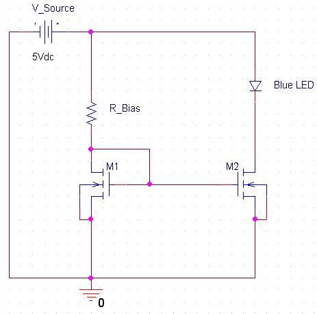
I wanna drive Blue-color 20mA LEDs, using the same driver circuit for each one.
Since the voltage-drop of such LED spreads over 3.0V to 3.8V, i decided to use a current source.

Here are the current source's specifications:
1. R_Bias sets IDS to 20mA.

2. M1 and M2 Mosfets are of the same type.

3. I'll choose the Mosfet so the output voltage swing (VDS2) will cover the range from 1.2V to 2V, meaning that either when the LED's voltage drop is 3.8V or 3V (respectively), M2 will remain saturated (constant current region).

What is your opinion?

Thanks alot.


current-source-jpg.33023
 

Attachments

  • current source.JPG
    current source.JPG
    19.5 KB · Views: 857
Last edited:
Hey,
Could you please explain what is this Vgs(off) mismatch you mentioned?

Thanks for the additional current source scheme.
 
Well, because in this current mirror circuit the Vgs_M1 = Vgs_M2.
So any mismatch in Vgs will cause Id_M2 will not be equal Id_M1
For example:
Id_M1=10mA for Vgs=3V but in M2 Vgs=3V (by Vgs mismatch) will cause Id_M2=20mA
 
I see now what you meant.

So what are current mirrors for if you cant use them in such way?
How much error should i expect if i order large quantity of the same Mosfet, and use each pair of them as a current mirror?
If the error is up to 10%, then its something i could live with, since the LED should still illuminate sufficiently with 18mA, and shouldn't get damaged with 22mA.

So from your experience, what is the largest error i should expect?
 
Since in that case i'll need to use a 100Ω resistor:
(5V - 3V) / 20mA = 100Ω.

I took the minimum voltage drop of the blue LED, since i dont want to burn it.

How can a 100Ω resistor be used to drive a 3.8V blue LED?

Thanks!
--
If you think that a different resistor should be used, i'd be glad to hear about it :)
 
Last edited:
You must look to the datasheet.
I built this circuit whit IRF540 and got 3mA error.

What was the original current that you wanted to have?
If the original current should have been 6mA then its a major error,
but if the original current should have been 100mA, then its only a 3% error.

I don't understand the questions?

I'll post up a scheme about it later this day.


Thanks!
 
The original current is 10mA so error is 30% (13mA).
And in your situation I would not bother myself with current source. Only use a simple 220R resistor.
 
Last edited:
I see now what you meant.

So what are current mirrors for if you cant use them in such way?
MOSFET current mirrors are typically found in integrated circuits, where matching is easily achieved.
Here's a 20mA BJT current sink that's pretty simple. It uses the Vbe of Q2 as a reference voltage. The output current is ≈Vbe2/R1.
 

Attachments

  • BJT current sink sch.PNG
    BJT current sink sch.PNG
    6.8 KB · Views: 736
The real disadvantage of the top circuit is wasting a lot of current. You should use what I call an unbalanced PNP mirror. Two PNPs with their emitters tied up top to the positive rail through degeneration resistors with their bases connected (one transistor is connected as a diode) and the collectors source current. On the diode collector, put a resistor to ground to set a current. On the other collector, put the diode to ground. TRICK: use emitter degeneration resistors on each PNP so the ratio of currents is like 10:1 so the LED gets most of the current. I'll draw it up if you are interested.
 
The real disadvantage of the top circuit is wasting a lot of current. You should use what I call an unbalanced PNP mirror. Two PNPs with their emitters tied up top to the positive rail through degeneration resistors with their bases connected (one transistor is connected as a diode) and the collectors source current. On the diode collector, put a resistor to ground to set a current. On the other collector, put the diode to ground. TRICK: use emitter degeneration resistors on each PNP so the ratio of currents is like 10:1 so the LED gets most of the current. I'll draw it up if you are interested.
R2 draws less than a milliamp as drawn, with 20 mA of output current. The bias current can be even less if desired.
The unbalanced current mirror as you described it apparently will waste 2mA for 20mA of output. Did I miss something?
There are many ways to make current sources (and sinks). I was just showing a simple one that has good headroom, with decently high output impedance.

EDIT: I didn't realize that you were apparently talking about the OP's MOSFET current mirror.:eek:
 
Last edited:
R2 draws less than a milliamp as drawn, with 20 mA of output current. The bias current can be even less if desired.
The unbalanced current mirror as you described it apparently will waste 2mA for 20mA of output. Did I miss something?
A ratio of 10-1 was just a number for example, you can set the ratio to anything you want if you adjust the emitter degeneration resistors accordingly and factor in the delta VBE based on the ratio of the two emitter current densities which is:

delta VBE = .026 natlog (I1/I2)

Now that I look at the 5V supply restriction, a PNP current mirror probably doesn't have enough headroom anyway.
 
Last edited:
MOSFET current mirrors are typically found in integrated circuits, where matching is easily achieved.
Here's a 20mA BJT current sink that's pretty simple. It uses the Vbe of Q2 as a reference voltage. The output current is ≈Vbe2/R1.
It looks like the LED current would try to be VBE/33 which is about 20 mA. The problem is that a VBE across the 33 Ohm resistor (and 3.8V across the FET) only leaves about 0.5V drop across the transistor which will put it close to saturation. It will have lower current gain and need more base current to support 20mA of collector current and it has to get that base current from R2.

EDIT TO ADD: at 20mA, the data sheet says the sat voltage is around 300mV with a gain of 10, so at 500mV VCE it might have decent gain (maybe 30?). It still needs to dump about 0.7mA out of the base. I would lower R2 to about 2K to give it headroom.
 
Last edited:
It looks like the LED current would try to be VBE/33 which is about 20 mA. The problem is that a VBE across the 33 Ohm resistor (and 3.8V across the FET) only leaves about 0.5V drop across the transistor which will put it close to saturation. It will have lower current gain and need more base current to support 20mA of collector current and it has to get that base current from R2.

EDIT TO ADD: at 20mA, the data sheet says the sat voltage is around 300mV with a gain of 10, so at 500mV VCE it might have decent gain (maybe 30?). It still needs to dump about 0.7mA out of the base. I would lower R2 to about 2K to give it headroom.
You make some good points. If this were a production unit, all of the above should be considered. As a one-off, it would probably work just fine.
We could replace Q2 with an op amp, and run the current sampling resistor with something like 100mV (or less) across it.:D
 
Status
Not open for further replies.

Latest threads

New Articles From Microcontroller Tips

Back
Top