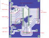
You need 0.1 uF bypass caps very close to each pair of power pins on the PIC. This is a common omission that leads to all sorts of
interesting problems.
Thanks Jon, this was the first thing i was supposed to add but forgot. Added them now
Also, are you sure that the crystal footprint is correct? The ones I use are > 0.2" spacing between the pins.
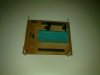
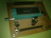
Yeah i know, but i have put female headers instead of crystals or any other components for that matter. I tried it and found that all components go in nice and are quite sturdy too!.
On my
TAP-28 board, I use separate 6-pin connectors for ICSP and UART- just swapping connectors is easier than flipping switches.
One trick I recently figured out when using the PICkit 2 and you just want a UART output to monitor program operation. Set up a software UART with pin RB7 as the transmit line. Then you can program in the usual way with the PICkit 2, then fire off the UART tool to monitor program operation
without switching anything! Just click CONNECT each time you start the UART tool. When you have new code to load, exit the UART tool, load it and switch back. Pretty slick.
I did however notice yesterday when using this trick extensively for the first time, some times the UART tool looked like it was working but I wasn't getting any output. Unplugging the PICkit 2, closing the GUI and starting over fixed it. I haven't figured out just what's causing this yet.


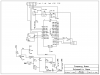
 . Otherwise its working fine(with an internal oscillator of course).