Electro Tech is an online community (with over 170,000 members) who enjoy talking about and building electronic circuits, projects and gadgets. To participate you need to register. Registration is free. Click here to register now.
Welcome to our site! Electro Tech is an online community (with over 170,000 members) who enjoy talking about and building electronic circuits, projects and gadgets. To participate you need to register. Registration is free. Click here to register now.
Hi, i wanted to know whether having a sufficiently large distance between the oscillator and the OSC pins in a PIC is ok or will it create problems? I am talking about distances around 2.5 to 3 inches and on a PCB board.
Hi, i wanted to know whether having a sufficiently large distance between the oscillator and the OSC pins in a PIC is ok or will it create problems? I am talking about distances around 2.5 to 3 inches and on a PCB board.
Thanks Nigel. I was thinking of building a universal Debug/ Programming/ Development target board for the PICKIT2(had this neat idea and thought of the time it would save and the flexibility with access to all pins and stuff). Well one can have it separate for 18, 20, 28 and 40 pin devices. I will make one for the 40 pin 18Fs than. Thanks again
Hi, i wanted to know whether having a sufficiently large distance between the oscillator and the OSC pins in a PIC is ok or will it create problems? I am talking about distances around 2.5 to 3 inches and on a PCB board.
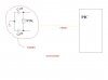
Hi 3v0, Driver300.. its a crystal oscillator and the caps will be placed next to it and these 3 elements would be at around 3 inches or less from the PICs OSC Pins. Actually i saw this guy with an arduino doing this debug thing using the serial port and i thought why not have a development/debug/programming target board for the PICKIT2(use its hardware debug capability) that gives access to all the PICs pins (has got female headers to insert wires) and allows for debugging in the circuit via a dip switch. I know i can have the oscillator right next to the PIC if i make separate boards pin wise(40, 28, and 18) but i thought if i could have the oscillator further away than i could make a general board for most if not all the PICs. Will upload a schematic and the art work to better explain it later today
Hi 3v0, Driver300.. its a crystal oscillator and the caps will be placed next to it and these 3 elements would be at around 3 inches or less from the PICs OSC Pins.
An oscillator is one element. It sometimes has a suppressor capacitor, but only one, and it connects to one oscillator pin on the PIC. The other one is left open or can be used for other stuff.
I think you have a crystal and two capacitors.
Let me outline the differences:-
Crystal.
2 connections.
Both connect to PIC crystal pins
Needs capacitors
no connection to +ve
examples Crystals | Farnell United Kingdom
Oscillator
3 connections
only 1 connects to PIC OSC pin
The others connect to +ve and ground.
A supressor capacitor can help
examples Oscillators | Farnell United Kingdom
Just go and buy an oscillator at the right frequency. They are so much easier to use.
(I only spent 20 years at a company that made oscillators)
Yes, it is generally a bad idea to put a crystal that far from the inverter that makes it oscillate.
The wires will pick up signals from each other and from the components and tracks that they pass on the way. The ground voltages won't be the same at the capacitors and at the PIC.
I suggest that you buy an oscillator, they are not expensive, or make one with two inverters, plus the crystal and the capacitors. One inverter is the oscillator and one is the buffer. The buffered signal can be sent much longer distances.
explains how oscillators start up. They really don't like noise when starting up, and start-up is slow compared to the rest of the circuit. During start-up, the signals are minuscule. The crystal amplitude increases exponentially until the oscillator circuit limits it, and so for the first 0.2 ms the amplitude is undetectable with an oscilloscope. The only reason that I am fairly sure that the signal is there and is getting bigger is that it eventually (0.5 ms or so) gets large enough for an oscilloscope to see, and shortly after that hits the circuit limits.
I think it's a bit like starting a fire. A match will light a forrest fire, but it takes hours to go from striking the match to an inferno, and in the first few minutes the fire is tiny and can be snuffed out easily.
In the first few hundred microseconds of an oscillator starting, the signals are small and feeble and delicate, and can be overwhelmed by the big nasty, noisy digital signals nearby, especially if you add a pair of 3 inch long ariels.
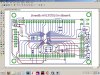
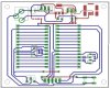
Hi 3v0 and jason, it would be my pleasure to share this. Here is the schematic, still working on the different combos about the oscillator and reset circuit types with jumpers and than will do the artwork part. It is supposed to work with all oscillator types and reset configurations, allow debug and programming without disturbing the circuit. I will add another header thing for PICKIT2s UART tool. When ever one needs to use an external crystal just place the crystal and the caps in the right female header and one is ready to go.
My version of a simple board, the TAP-28, is somewhat different than most. I've designed the board to have connectors for hardware functions so the board is aimed at applications in the real world. Sensors, I2C/SPI boards or boards using UART coms can be hooked up by connector for long-term reliability.
The board has a couple switches and 4 LEDs which are useful during programming and during use. Other features not usually required for embedded applications have been left off the board to keep the cost low.
**broken link removed**
The boards are available inexpensively on the TAP-28 web site or I'll provide Gerber files for anybody who would like to make their own.
I have a couple recommendations, depending on how big your boards are and how many you want to make.
PCBGeek.com will make as many copies as will fit in 200 in. sq. for a total of $89 (to the US). Excellent results. The exact number of boards depends on how yours fit on their panel.
PCBCart made the boards above. They'll quote on any size board and quantity. If making a lot of boards, their pricing is excellent. Shipping is going to make a small quantity expensive.
PCBFabExpress has provided good service for small quantities of boards. Mention my name and I might get a referral credit
Sparkfun offers their BatchPCB service. I've never tried them but for very small boards and small quantities, they look like a good deal.
Dorkbot will provide 3 boards for $5/in. sq. They order panels when the batch fills up, so it can take some time to get boards. I've also heard the solder mask and silk screen are whatever they happen to be making when the boards are done, so you take what you get.
I don't know how shipping to Trinidad will be handled by any of the above. The first three sources I have used myself. The last two I have not. A lot depends on quantity and size, so what's a good deal for my might not be for you.
This site uses cookies to help personalise content, tailor your experience and to keep you logged in if you register.
By continuing to use this site, you are consenting to our use of cookies.

")