Continue to Site

Welcome to our site!

Electro Tech is an online community (with over 170,000 members) who enjoy talking about and building electronic circuits, projects and gadgets. To participate you need to register. Registration is free. Click here to register now.

  • Welcome to our site! Electro Tech is an online community (with over 170,000 members) who enjoy talking about and building electronic circuits, projects and gadgets. To participate you need to register. Registration is free. Click here to register now.

Corona discharge in Sony Trinitron CRT TV

Status
Not open for further replies.
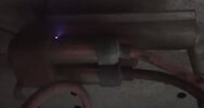
I recently got a free Sony Trinitron KV-27TS20 CRT TV (assembled in San Diego in April 1990). I opened it and didn't see anything obviously broken. The "serviceman label" insides says that the anode potential is 28 kV. It works when powered on, but there's a corona discharge from a part that's located between the flyback transformer and the anode cap (see attached photo).

I can't find a service manual for this particular model, and similar models don't seem to have this part. What is this part (shown in the attached photo) and what's its purpose? Is the corona discharge caused by damaged insulation, or is it a symptom of a more serious problem?
 

Attachments

  • Sony-Trinitron-KV-27TS20-Corona-Discharge.jpg
    Sony-Trinitron-KV-27TS20-Corona-Discharge.jpg
    43 KB · Views: 444
The photo is really useless, it's so poor that you can't even tell what it is.

But, there are pretty well two options between LOPTX and anode cap - a high value discharge resistor, or a high voltage capacitor to improve EHT regulation.

A third option would be if there's an adjustment on whatever it might be, some Trinitron sets had such an adjustment, either on the CRT base, or in the EHT lead, and was a kind of static convergence adjust as I recall?.

However, you got it 'free' because it's completely worthless, it's difficult to even give CRT sets away, even if perfectly working.

It's not a sign of anything else, just insulation breakdown, but it's not a good idea to use a set in that condition - either replacing the part, or repairing it, is needed.

There's also the option of completely removing it, assuming it's one of the first two option?.
 
I recently got a free Sony Trinitron KV-27TS20 CRT TV (assembled in San Diego in April 1990). I opened it and didn't see anything obviously broken. The "serviceman label" insides says that the anode potential is 28 kV. It works when powered on, but there's a corona discharge from a part that's located between the flyback transformer and the anode cap (see attached photo).
That's likely a voltage doubler, and the discharge is an easy fix; clean it off and paint
over it with some high voltage varnish or Q-dope... taking, of course, all the
usual HV precautions like discharging and grounding the anode of the picture tube.
 
That's likely a voltage doubler, and the discharge is an easy fix; clean it off and paint
over it with some high voltage varnish or Q-dope... taking, of course, all the
usual HV precautions like discharging and grounding the anode of the picture tube.

I've never seen an external voltage doubler on a Sony TV (or on any other I can recall), so I would say almost certainly not. Anything remotely 'modern' has the rectifiers and any multiplier (almost always a tripler, not doubler) inside the LOPTX, using a technique called 'diode split'. Other wise it's normally just a half wave rectifier inside the transformer. 'Old' colour sets used external triplers, and then cheaper ones started using external half wave rectifiers.

It's also not as simple as you make out to stop discharge once it's started, it often takes a lot of work to make a long lasting repair.

As I mentioned earlier, some Sony's did have an external control in the EHT lead - the EHT lead was coaxial, so had an inner and outer contact, with the pot varying the voltage between them. But as I said, his photo was so poor it's impossible to tell what it is.
 
As I suspected, it's either a discharge resistor, or a high voltage capacitor - the set would work fine without it, but you've then got the issue of what to do with the wires, how to join them, and how to prevent that join arcing.

I'd be inclined to try and seal the leak, see if you can cure it that way - first job, make sure the CRT is discharged - standard TV engineer way is two screwdrivers. One to the aquadag, then slide the other across that one and underneath the anode cap - that cap should be a single connection, so no problems.

If you remove the cap, then fit a croc clip lead from cap to the aguadag wire/spring to keep that discharged, and do the same with the end of the EHT lead.

The shock from EHT isn't particularly 'dangerous', as it's too low a current - but falling over and breaking your neck as a result is just as fatal.

Then clean the faulty component really well with alcohol, IPA or something similar - then discharge the CRT again (they tend to self recharge - so keep doing so occasionally). I would then grind the offending area away carefully with a Dremel, as the plastic probably has a carbon track burnt in it, and you need to get rid of that - go as deep as required to get rid of it all, without damaging the component inside the plastic.

This should give you a nice clean hole, with good adhesion - fill this with epoxy resin (5 minute epoxy glue), and fill it proud with a nice dome on the outside.

Let it set - I would give it overnight, then you should be good to go.

Incidentally, for anyone else reading this in the future - if you have a similar issue and the device has a control on it, this means that the EHT lead and cap is coaxial, this requires a special tool to remove, which is an SRBP wedge/fork type device that squeezes the outer coaxial connections together to unhook them (we used to have a handful of them sat in a draw at work). Trying to remove it without could damage the cap, and the CRT connection.
 
I much appreciate your insightful response! I will follow your advice on how to repair the insulation. When I got this CRT TV I assumed it was dead and planned to scrap it for parts. I was very surprised that it powered up at all. I will attempt a restoration, and probably try to add composite-video input as well (for some retro gaming).

Thank you!
 
Just a word of warning - make absolutely sure it's not a live chassis set - although very few were by that time, it wasn't 100% of sets that were isolated. And it's rather suspicious that the set doesn't already have an AV input?.

One simple check is the aerial socket - which isn't very visible in the picture - is there an aerial isolator on the end of it?, if so it's live chassis.

Most sets, by the time of this one, had a non-isolated socket actually on the tuner itself, which was mounted at the rear of the set so the socket poked through.
 
Thanks, I'll make sure it's isolated before proceeding. It's a Sony from 1990, assembled in the US, so it should be safe, but I'll check nevertheless. The lack of component-video input is normal for CRT TVs for the US market. An F-type coax connector for RF input, and three RCA connectors for composite video (NTSC), left and right audio channels, respectively, is par for the course. It's a common mod to retrofit RGB video input.
 
It works when powered on, but there's a corona discharge from a part that's located between the flyback transformer and the anode cap (see attached photo).

As I suspected, it's either a discharge resistor, or a high voltage capacitor - the set would work fine without it, but you've then got the issue of what to do with the wires, how to join them, and how to prevent that join arcing.
that device is a voltage tripler/rectifier. sony used them in a lot of their Trinitron TVs, and they were a high failure item. using a tripler allowed the use of a lower voltage FBT without having diodes and capacitors embedded in the FBT. other TVs of the time had 30kV FBTs with an inline rectifier, and the higher voltage FBTs were much more expensive and less reliable than a 10kV FBT.
 
Last edited:
Status
Not open for further replies.

Latest threads

New Articles From Microcontroller Tips

Back
Top