Electro Tech is an online community (with over 170,000 members) who enjoy talking about and building electronic circuits, projects and gadgets. To participate you need to register. Registration is free. Click here to register now.
Welcome to our site! Electro Tech is an online community (with over 170,000 members) who enjoy talking about and building electronic circuits, projects and gadgets. To participate you need to register. Registration is free. Click here to register now.
3iMaJ,
I am not trying to measure any Doppler shift. I am looking for an object within a zone but there are lots of reflections from false targets--lots of metal in the area. I would like to take a background reading and create a window around the background. If there is a significant change within my zone of interest, then I know I have an object within the target zone that is not part of the 'noise'. I would like the circuit to be as small and simple as possible.
Edit:
I thought I was responding to 3iMaj, but his message just disappeared when I posted my reply [I just noticed that it was on page 1]. In response to some of the other comments, I am not going to transmit the data. The PIC will analyze the waveform to discern the presence of an object from noise within a target zone.
I actually have two different applications. The first is a pulse-echo application with lots of false targets. The second has a separate movable transmitter and the receiver needs to return an accurate time of flight that is consistent from location to location. I.E., it will always trigger on the same pulse# within the transmitted 40 KHz burst. In that case, I think I might look for the first decayed pulse which should indicate the end of the transmitted 40 KHz burst (unless it continues to ring at near-full amplitude for an inconsistent number of pulses). My concern with simply triggering is that the attenuation may be different from location to location and I would get inaccurate results using a leading pulse for a trigger (while the transmitter starts to resonate and builds up amplitude). I am not worried here about false targets because the first arrival will be the shortest distance. For this application, I want as accurate a distance measurement as possible. Each pulse means almost 1 cm difference in distance.
DSG
If you're just doing a detection problem you should probably calculate what the optimal detector needs to be rather than just design a detector that will work. You will probably find that there is a large difference in performance between the two detectors.
Its probably safe to assume that your noise is awgn, and as such the detection problem should be quite easy to solve, just a maximum liklihood detector, however if you're trying to discern one target from another it might be a little more complicated.
It may be that the optimal detector is just a peak detector, however knowing where to put the threshold will depend on what you measure the noise power to be. However, if there is a lot of multipath you need to take great care in your detector because you could get a lot of false alarms or misses depending on how the detector is designed.
The production version of my circuit will use SMDs. Thru-hole are desirable for prototypes. I noticed several of the DS PICS had both package versions and I don't mind paying an extra buck or two for a more capable device especially if it is offered in multiple packages.
DSG
Why to get rid of the 555 of course, most PICs have comparator inputs that might work just as well. Timing done digitally too.
The PIC also has a sample & hold cap built in. No real need for the CD4016.
Lastly the PIC needs a low 2.5K input impedance to convert at full speed.
Why to get rid of the 555 of course, most PICs have comparator inputs that might work just as well. Timing done digitally too.
The PIC also has a sample & hold cap built in. No real need for the CD4016.
Good question, I would think 4us was fine for this application, the comparators are connected to an interrupt and A/D coversion is a one shot deal. A/D conversion can be speeded up at the cost of accuracy.
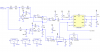
I have almost zero experience with PICs. I have simulated the circuit I presented, and it works (in simulation). I can't simulate this function with a PIC incorporated, and I don't have the time or the resources to breadboard it. If you do, go for it.
Can you post an simulated image of the pin #2 signal?
I don't have the time or inclination to do the OPs project for him. I'll help but I'm not going to build the thing.
PS I wonder if the OP has the programming skills required to complete the project?
Can you post an simulated image of the pin #2 signal?
I don't have the time or inclination to do the OPs project for him. I'll help but I'm not going to build the thing.
PS I wonder if the OP has the programming skills required to complete the project?
This site uses cookies to help personalise content, tailor your experience and to keep you logged in if you register.
By continuing to use this site, you are consenting to our use of cookies.