Continue to Site

Welcome to our site!

Electro Tech is an online community (with over 170,000 members) who enjoy talking about and building electronic circuits, projects and gadgets. To participate you need to register. Registration is free. Click here to register now.

  • Welcome to our site! Electro Tech is an online community (with over 170,000 members) who enjoy talking about and building electronic circuits, projects and gadgets. To participate you need to register. Registration is free. Click here to register now.

Convert TDA2030 to DC Coupled, Wholely Positive Voltage Output

Status
Not open for further replies.
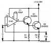
Yes, you are all correct. I thought I could simply modify the existing split supply TDA2030 device. Now I can see it will be more straightforward to just build a single supply, DC coupled op amp and emitter follower (see attached).

I should have made it clear at the beginning that I was not driving a speaker, even though one was shown in the generic circuit diagram I linked to. If the output swing is not bipolar, and has no DC component, I assume no decoupling cap is needed at the output.

Alternatively, I could stick with the TDA2030 circuit and add enough series resistance so the DC resting at 6V does not overload the output. Obviously not very efficient though.
 

Attachments

  • s20097101281782.gif.jpeg
    s20097101281782.gif.jpeg
    24.6 KB · Views: 135
Maybe you should be drawing the pictures.
1) Remove the negative is not right.
2) Offset is/is_not right.
3) Rectification, no comment.
1551012013884.png

Now we are back to this: Which removes the negative. Was rejected before.
1551012216369.png

I know this Keysight signal generator very well. It has a "offset" function to make the wave form shown with out the transformer.
What the transformer does is exactly what has been shown before. Just move the "0" point to 6V.
1551012455750.png

What makes this sub audible signal?
 
Your antique opamp driving a little transistor that drives a monster very high current transistor has no +6VDC input offset voltage so the circuit is simply rectifying the sinewave.
 
Your antique opamp driving a little transistor that drives a monster very high current transistor has no +6VDC input offset voltage so the circuit is simply rectifying the sinewave.

Being a bit of an antique myself, I have used similar circuits when the input signal is monopolar. For example from a function generator and not line audio. I would, by normal practice, add an input offset for the latter.

With regard to Ron's comment about the transformer, while the "0" point is shifted, it would appear the current to do so is provided by an external DC supply and not the amp.

The signal I am intending to amplify contains both sub and low audio. The source is a type of magnetometer. Since these files are recorded, and played from an MP3 device into the amp, the signal input to the amp is bipolar. All I wanted to do by modifying the TDA2030 was to convert its output signal back to monopolar, as per the original magnetometer output.

The original circuit diagram shows a +/- 15VDC supply. How about adding some of the positive rail voltage to the TDA2030's output to offset it by +6V so that the offset current is provided by the supply and not the amp?
 
You can use a TDA2030A if you want. In your circuit on page 1 of this thread its gain is 1 + (47k/1.5k)= 32.333 times so for an output offset of 6V then its input pin2 must be -6V/32.333= -0.1856V with a resistor to -15V as shown in post #5.
 
and played from an MP3 device into the amp,
Is the MP3 player good at DC? or 1hz? I am asking if you know if the MP3 can do very low frequencies.

How about adding some of the positive rail voltage to the TDA2030's output to offset it by +6V so that the offset current is provided by the supply and not the amp?
I think the coil current must pass though the TDA2030 anyway.
 
I find that cheap MP3 players, like Chinese copies of the iPod, will do ELF down to a few Hz. Probably just poor filtering. Not sure about DC though ;-)

In case it was unclear, my meaning was to offset the TDA2030 after its output. It seems you are saying that would still load the amp with the offset DC component. Not sure why that could happen since the amp is not the offset voltage source.
 
The signal I am intending to amplify contains both sub and low audio. Since these files are recorded, and played from an MP3 device into the amp, the signal input to the amp is bipolar. All I wanted to do by modifying the TDA2030 was to convert its output signal back to monopolar, as per the original magnetometer output.
An MP3 plays audio sounds not earthquake rumbles. Its output level will drop at 20Hz and reduce lower frequencies much more. Your results will be a 28Hz drum with a random beat.

How about adding some of the positive rail voltage to the TDA2030's output to offset it by +6V so that the offset current is provided by the supply and not the amp?
The TDA2030A and all other audio amplifier ICs have an extremely low output impedance. If you try to force its output then it will fight back and cancel it making lots of heat.
 
An MP3 player will not play earquake rumbles, it will play music down to 20Hz and cut lower frequencies a lot.

Your coil will have a very low resistance to your +6V offset voltage which will need a very low resistance to make +6V feed the coil.
The TDA2030A and all other audio amplifier ICs have an extremely low output impedance. If you try to force its output with a DC offset then it will fight back and cancel it making lots of heat.
 
my meaning was to offset the TDA2030 after its output.
If the "0" point of the amp is +6V, then play with the value of the 28 ohm power resistor so that the load and the new resistor divides the 15V down to near the same 6V. This way some of the power that is needed is shunted round the power amp and directly to the load.
1551058776073.png

The new resistor will run hot but the TDA2030 will cool off.
 
I checked the MP3 player at hand on the scope. It does pass ELF's reasonably well. There are also sound modules that play MP3's from a micro SD card, most based upon the WTV020SD chip. I find the Chinese ones, costing a few dollars on eBay, tend to be finicky in use. Those from 4D Systems are much better in terms of build and reliability.

Thanks Ron. I will give that a try. I always learn new things on the road less taken (likely for a good reason). Time now to spend a few hours at the bench.
 
The output of the amplifier has an extremely low output impedance (0.04 ohms or less) and will use all its power to keep the average output voltage at 0VDC. In order to offset its DC output at +6V then you need to add a series resistor between the amplifier output and the 28 ohms resistor but the resulting voltage divider reduces the signal output voltage swing.
It is much better to offset the inverting input and let the amplifier amplify it to an average of +6VDC.
 
Status
Not open for further replies.

Latest threads

New Articles From Microcontroller Tips

Back
Top