Electro Tech is an online community (with over 170,000 members) who enjoy talking about and building electronic circuits, projects and gadgets. To participate you need to register. Registration is free. Click here to register now.
Welcome to our site! Electro Tech is an online community (with over 170,000 members) who enjoy talking about and building electronic circuits, projects and gadgets. To participate you need to register. Registration is free. Click here to register now.
If you use a 0.22 :mu:F capacitor (non polarised and rated to at least 300 V) then the current will be the same and there won't be nearly as much power dissapated.
The capacitor will be seeing up to 339 volts in normal operation, so a 300V device is clearly inadequate. The capacitor rating needs to be rated at least 600V, and should also be rated for connection to the AC mains.
You still need a small series resistor to limit the current when there are glitches on the line.
You need to use a "X2" rated capacitor, a non polarized capacitor rated
for 300 volt is not designed for 230 Vac/50Hz operation, check the datasheet
for this capacitor. You'll also need a bleeder resistor to discharge the
capacitor when power is switched off, preferably a high voltage resistor
(about 10 Meg is ok).
And you will also need to connect a resistor in series with this capacitor
to limit the inrush current to a safe value for the led/diode, preferably
a fusible resistor (select a value between 1k and 2k2/0.5W). These "special"
resistors cost a bit more than the regular resistors but if you want to be
safe at all times it is money well spent.
What...???
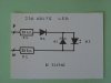
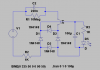
You can light up a 3.6V DC LED directly from 220VAC just by using some diodes, capacitor and resistor without using any sort of step down transformer..?
WOW...
Sorry.. I am new to this.. umm.. can somebody kindly explain the concept or point me to where I can know more about this..?
Thanks..
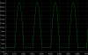
The LED is powered with half-wave so it will flicker at 25Hz and drive you crazy.
Use a rectifier bridge to eliminate the flickering and then a filter capacitor can also be used. The series capacitor that limits the current with its capacitive reactance will then need to be half the value before.
Interesting..
I see.. most of the voltage drop is accross the 10M resistor.. The LED only receives a small portion of the 220V voltage..
Hmm.. jst wondering.. how about powering the PIC MCU using this method..?
Attaching a full bridge rectifier circuit between the 10M resistor and 1K resistor, 5V voltage regulator and capacitors to smooth the ripples..
What are the disadvantages of that apart from accidentally touching the 10M resistor and high power dissipation..?
The power dissipation is actually pretty low, about 300mW.
The apparant power is 3.3VA.
The power factor is very poor at only 0.091. You could improve this but you'd need to add a large inductor which would be very bulky and defeat the purpose of having a light weight power supply.
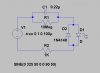
Actually that's not true I believe [for the first diagram]
The 10M has little effect on the circuit, you see capacitors have a resistance to low frequencies, this is called reluctance rather than resistance because unlike resistance no power is dissipated in the capacitor.
The Formula shown below determines the reluctance for a capacitance.
Xc = 1/(2 * Pi * F * C)
Xc = 1/(2*Pi*50*220nF)
Xc = 14.4Kohm
This is in parallel with 10M, because 10M is so high it makes little difference to the resistance.
14.4K + 1K because its in series with the 1K resistor is
15.4K
current = 230 / 15.4 = 15mA
Seems a little low to me.
Edit:Whops I was using RMS value
root(2) * 230 = 425V
425 / 15400 = 21mA.
Both capacitors (Xc = 1 / (2 pi F C) and inductors (XL = 2 pi F L) have reactance. If you have an inductor and a capacitor in series the total reactance is de difference of them (Total X = XL - Xc)
This site uses cookies to help personalise content, tailor your experience and to keep you logged in if you register.
By continuing to use this site, you are consenting to our use of cookies.


")
 hm: 1 Watt resistor