Continue to Site

Welcome to our site!

Electro Tech is an online community (with over 170,000 members) who enjoy talking about and building electronic circuits, projects and gadgets. To participate you need to register. Registration is free. Click here to register now.

  • Welcome to our site! Electro Tech is an online community (with over 170,000 members) who enjoy talking about and building electronic circuits, projects and gadgets. To participate you need to register. Registration is free. Click here to register now.

Controlling a Single Phase Motor (Refrigerator Compressor) using PWM

Status
Not open for further replies.
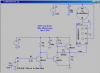
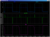
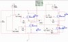
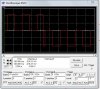
we want to amplify the amplitude because we discovered something in our simulation. PWM input to an IGBT (we used IGBT to function as a switch w/ PWM as the input to its gate) we plan to let a 220VDC through the transistor and it will be switched on and off through PWM. What we discovered was if our PWM input was only about 5-10Vpp the voltage that the IGBT lets through was approximately 5-10V as well... so we changed the PWM to about 100Vpp and then suddenly the voltage that comes through became 199-215V...

Is this a concept in a transistor?
 
Alright Thanks! um do you know any schematic on how to drive an IGBT? i believe that its the current that counts when you want to turn on the device, is that right?
 
Here is a low-side IGBT gate driver that I built into my airplane mover. It uses a 1/4HP 130Vdc GearMotor. I am using a PIC to PWM it at about 10kHz to smoothly control the acceleration/deacceleration. Picture here.

The green trace is the current into the gate of the IGBT. It takes a driver with a current drive of ~1/2A to rapidly charge/discharge the IGBT gate capacitance.
 

Attachments

  • TMDa.png
    TMDa.png
    29.7 KB · Views: 419
  • TMDb.png
    TMDb.png
    26.5 KB · Views: 378
Last edited:
Hi MikeMl thanks for the schematic! our group is trying to drive a motor with an H-Bridge configuration... I also tested your circuit and it works fine when the load (i just used a resistor) is in the COLLECTOR side. I tried transferring the load to the Emitter side and the voltage output was very low. Is it really like that?

Thanks!
 
how do you post images, it says here it needs a URL link? does it have to be in tumbler or websites like that? (we are new here sorry)
 
Hi MikeMl thanks for the schematic! our group is trying to drive a motor with an H-Bridge configuration... I also tested your circuit and it works fine when the load (i just used a resistor) is in the COLLECTOR side. I tried transferring the load to the Emitter side and the voltage output was very low. Is it really like that?

Thanks!

Read the Name on the schematic I posted: LOW-SIDE DRIVER! It drives the gate of the FET/IGBT to 12V with respect to its source. It was never intended to be used to drive the high-side of an HBridge.

Why are using an H-Bridge, anyway? Don't you just have a DC motor that always turns one one way? You only need an H-Bridge if you are reversing the motor.
 
We plan to apply it to an AC Motor, is it not applicable? Another question, doesnt an IGBT acts as a switch? so when it turns on, it sort of turns into a closed switch where it will let voltage flow from collector to emitter? Thanks
 
This is the circuit that we simulated, the 500ohm is like our "MOTOR" and we switch the igbt's on and off correspondingly for it to become an AC.
 

Attachments

  • IGBT h-bridge.jpg
    IGBT h-bridge.jpg
    351.5 KB · Views: 740
  • output on load.jpg
    output on load.jpg
    78.8 KB · Views: 345
You were told in the first three posts in this thread that this entire enterprise is a fool's errand.

The project has become: Lets learn how to make a Variable Frequency Motor Drive controller[/I]. If I really thought I needed a VFD, I would just buy one.
 
Status
Not open for further replies.

Latest threads

New Articles From Microcontroller Tips

Back
Top