Hi - I'm a newbie
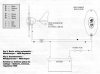
I am fitting a small wind turbine (in a school) that is being used to charge a 12V car battery; the voltage is kept at 12V - the current increases with windspeed (0A - 6A @ 12V).
I want a light-based display that will indicate the increasing current as the windspeed increases. I thought of using the changing current to control a flasher circuit (more current = faster flashes) or an led bar display, but despite hunting though my electronics library and the internet, I can't find any circuits controlled by current! Any suggestions welcome! Thanks Dave")
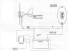
I am fitting a small wind turbine (in a school) that is being used to charge a 12V car battery; the voltage is kept at 12V - the current increases with windspeed (0A - 6A @ 12V).
I want a light-based display that will indicate the increasing current as the windspeed increases. I thought of using the changing current to control a flasher circuit (more current = faster flashes) or an led bar display, but despite hunting though my electronics library and the internet, I can't find any circuits controlled by current! Any suggestions welcome! Thanks Dave