Continue to Site

Welcome to our site!

Electro Tech is an online community (with over 170,000 members) who enjoy talking about and building electronic circuits, projects and gadgets. To participate you need to register. Registration is free. Click here to register now.

  • Welcome to our site! Electro Tech is an online community (with over 170,000 members) who enjoy talking about and building electronic circuits, projects and gadgets. To participate you need to register. Registration is free. Click here to register now.

controlling a circuit using a changing current

Status
Not open for further replies.
hi Dave,

Have a look over this circuit.

Any questions please ask.

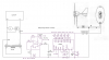
The LM3914 is configured as a DOT display and when set up correctly it should indicate as follows.

No wind, no charge, no leds lit.

Charging at 0.5Amp, led#1 lit, charge 1Amp led#2 lit and so on upto 5Amp when led#10 is lit.
 

Attachments

  • DaveChgr1.png
    DaveChgr1.png
    98.6 KB · Views: 178
Sounds great - Yes, I use veroboard - is it too difficult to change it so that it is a barchart rather than a dot display -from where the kids will see it routinely (the project is based in a courtyard in the middle of the school and the kids won't be allowed in unsupervised) a dot display won't be as impressive, though if it is an issue (current drain, circuit complecity etc) I can make a very visible scale at the side of the LEDs
 
As my granny used to say - "bugger me": I've just looked at the diagram - stunning! DAve
 
As my granny used to say - "bugger me": I've just looked at the diagram - stunning! DAve

hi,
Its easy to change to bar, a single wire repositioned.
I opted for a dot just to keep the current to a minimum.
You could use high brightness leds, blue looks cool.!

Do you think you can build it OK.?

If you want to proceed, let me know I'll sketch a vero layout.
 
I like the idea of dot mode @ high brightness (8mm -10mm leds?) and perhaps two in parallel at 90 degrees to each other to give a wider field of view. i.e. the led's at 45 degrees to the mounting wall and 90 degrees between them - in dot mode I can "afford" the extra current drain of twice two led's on at any time.

One concern - Will the regulator mess things up by limiting the current we are measuring as the battery approaches full charge?

I'm really looking forward to assembling the circuits. The last couple of circuits I built have been running (as they say) 24/7 x 365 for 20+ years - being flashers controlled by 555 chips in alarm boxes - I'm not being cocky, just amazed at the reliability of electronic components! Dave
 
One concern - Will the regulator mess things up by limiting the current we are measuring as the battery approaches full charge?
Yes, I would assume the regulator reduces the charge current as the battery becomes charged. You could perhaps instead monitor the generator current but that depends upon how the regulator controls the battery charging current; whether it just dumps the excess current into a load resistor or actually reduces the generator current.
 
One concern - Will the regulator mess things up by limiting the current we are measuring as the battery approaches full charge?
Dave

hi,
The regulator is designed to reduce the voltage/current to the battery as the battery becomes fully charged, thats what its supposed to do.

If the regulator kept pushing current into the battery when it was fully charged it would over charge, cause gassing and possibly damage the battery.

As one would expect the current will reduce as the battery nears its fully charged state and the LM3914 leds will indicate this reduction, which I would expect is what you want.??

Im assuming the battery is a sealed lead acid.?

EDIT:
I like the idea of dot mode @ high brightness (8mm -10mm leds?) and perhaps two in parallel at 90 degrees to each other to give a wider field of view. i.e. the led's at 45 degrees to the mounting wall and 90 degrees between them - in dot mode I can "afford" the extra current drain of twice two led's on at any time.

Dont confuse high bright leds with the higher current versions.
The led current will be limited to approx 10 to 20mA.
Also dont put two leds in parallel.!
You can have two leds in series on the same LM3914 pin
The current will be the same whether its one or two leds, when in series.
 
Last edited:
oops - one of the LED's would hog the current I suppose

What I really wanted was some thing to show the possible current vs windspeed, or changing voltage vs windspeed, but of course the whole point of the setup is that the voltage is constant and the current isn't needed when the battery is charged!

However, seeing the recharging of the battery, though not happening all the time and not being directly related to windspeed, is still a very useful thing to do. To jazz the display around the clock up a bit, I can use the battery to run some LED's on a chaser/sequencer circuit, which can presumably be added in a similar way to the clock power circuit.

I've downloaded the layout designer - looking forward to having a play this weekend! Thanks for the suggestion

I've found a calculator for finding the resisitor values to give 1.5V for the clock. I know that you are doing all the work, but I'm really enjoying making sense of it all!

Dave :)
 
hi Dave,

Look at this image, check it thru.:)

Attached is a LM3914a.txt file, download it and then change the name to
LM3914a.diy, it will then be readable with DIY Layout Creator, have a play.!:)

Are you going to use Blue LED's.???

Note: you cannot place 4mm LED's on a 0.1inch pitch.
 

Attachments

  • LM3914a.txt
    6.8 KB · Views: 162
  • DaveChrgLay1.gif
    DaveChrgLay1.gif
    57.3 KB · Views: 194
Last edited:
Hi - I'm a newbie

I am fitting a small wind turbine (in a school) that is being used to charge a 12V car battery; the voltage is kept at 12V - the current increases with windspeed (0A - 6A @ 12V).

I want a light-based display that will indicate the increasing current as the windspeed increases. I thought of using the changing current to control a flasher circuit (more current = faster flashes) or an led bar display, but despite hunting though my electronics library and the internet, I can't find any circuits controlled by current! Any suggestions welcome! Thanks Dave :)

Hey BJT's are current controlled devices. You can take BJT based LED or something similar and use it.

Anyhow best of luck for your project.
 
Downloaded and converted! I'm now trying to relate the schematic to the layout :)

A couple of queries: R9 is coded as RxR
C1 is coded as 1uFpF
C2 is coded as 470uFnF
- I'm assuming u = micro(n), p = pico and n = nano so is, for example, C1 a 1 microFarad or 1 picoFarad or am I missing something?

I'm also unsure about the wires:
Is -B to the negative battery terminal?
Wire 3 (looks red) to the positive battery terminal?

Does wire 2 connect track s to track v or is it connected to track s and supposed to connect to something off the board? Track v doesn't seem to be connected to anything else
Similarly for wire 4 (pale orange) does it connect tracks e and f?

Dave :)

hi
R9 will be determined when we know the LED forward volatge drops.

The coding on the program has gone a little strange.!!!
C1 = 1uF
C2 = 470uF

-B is the battery neg - terminal [green] track 's'
+B is the battery pos + terminal [brown] track 'f'
The -Charge Reg wire goes to the 's' track , end of the R1 resistor
The +Charge Reg [fuse] goes to track 'f'

I always put the wire 'label' at the free end of the wire,,, the end that goes off the pcb.

Hope thats clear.:)

When we finalise the design and layout we will make the component labels correspond on the dwgs.
 
Hi - sorry for the delay in replying!

I've been back to the school I'm building this for and they have decided that since the kids will see everything during the day, they want bright rather than "cool" LED's. :( Therefore I'm going to use 8mm or 10mm Superbright red LED's from Maplins (depending on what they have) They are made by Kingfisher and have a Forward Max Voltage of 2.5V and a Forward Max Current of 30mA. I am going to mount the circuit board inside a weather sealed box where the rest of the electronics and the battery will be and run the LED's out on flying leads to where the clock will be mounted

I might sneak a couple of 5mm blue LED's in a rainbow chaser display to jazz up round the clock when the battery isn't charging! ;)

A question: What will happen if the battery is flat and it's very windy and charging current exceeds 5A (and all the LED's are lit) - fried chips wouldn't be very nice! The turbine can push out in excess of 6A according to the spec? :eek:

Dave
 
Hi - sorry for the delay in replying!
A question: What will happen if the battery is flat and it's very windy and charging current exceeds 5A (and all the LED's are lit) - fried chips wouldn't be very nice! The turbine can push out in excess of 6A according to the spec? :eek:

Dave

hi,
IMO the LM3914 would be well over stressed at 30mA for all 10 LED's in bar mode.
The circuit I suggested is not suitable for the revised application.
 
OK - I'm flexible! What LED's could I use? I only wanted the biggest because they would be the most obvious, but I can happily go for smaller/less bright! What aspect of the LED's is too much? The standard 5mm LED's that Maplins sell are 2.5V and 25mA. Could we miss out some of the LED's and just have 5, 6 or 7 etc? Dave
 
OK - I'm flexible! What LED's could I use? I only wanted the biggest because they would be the most obvious, but I can happily go for smaller/less bright! What aspect of the LED's is too much? The standard 5mm LED's that Maplins sell are 2.5V and 25mA. Could we miss out some of the LED's and just have 5, 6 or 7 etc? Dave

hi,
Its the current thru the leds/LM3914, look at this graph, I would suggest we stay within the 20mA limit.
Im using high bright Blue leds at 12.5mA and I can see them very clearly in daylight from about 5 mtrs.!

I think if you limit the number of leds to 5, its only going to show 1 amp increments.

EDIT:
you could do a bench test with a resistor set to give 20mA thru a 8mm or 10mm Superbright red LED.

From say a 12V supply, use a 470R resistor to one red led, see if it meets the brightness required. Dont forget you could have two in series on the LM3914
 

Attachments

  • esp01 Feb. 11.gif
    esp01 Feb. 11.gif
    12.4 KB · Views: 125
Last edited:
Since I intend to have two in series would this reduce the current enough to stick with the big LED's without a limiting resistor? (I know I could breadboard this, but I haven't got the LED's yet!) The students will be looking up to 12 metres away from inside the school to the far wall of the enclosed courtyard

I'm just about to check the Maplin catalogue for <20mA LED's!

Dave

The current thru the leds is fixed by that R1 [2K0] at about 10mA at the moment.
Having two leds in series will have the same current.
The LM3914 is a constant current output.

The resistor isnt to limit the led current, its to reduce the heating of the LM3914.

Its a pity you didnt mention the 12mtr visibility requirement earlier.
 
Last edited:
The only ones I can see in the Maplin's catalogue at 20mA or below are 5mm extreme brightness @ 50p each, or 5mm standard violet or turquoise @ £2.50 each!

Perhaps limiting resistors or 2 LEDs in series might be the answer :confused: - I've just had an exciting few minutes on my breadboard and 2 LED's in series drop the current! (I told you that I am a newbie :))
 
Status
Not open for further replies.

Latest threads

Back
Top