Continue to Site

Welcome to our site!

Electro Tech is an online community (with over 170,000 members) who enjoy talking about and building electronic circuits, projects and gadgets. To participate you need to register. Registration is free. Click here to register now.

  • Welcome to our site! Electro Tech is an online community (with over 170,000 members) who enjoy talking about and building electronic circuits, projects and gadgets. To participate you need to register. Registration is free. Click here to register now.

Controlling a 12v 80 watt dc motor with an Arduino

Status
Not open for further replies.
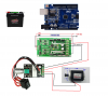
Any help would be appreciated what I want to build may be simple for some one out the there that's been using the Arduino for a wile now. I've never used one before but was told I could get help here .I haven't bought any parts yet because I want sure what to get .Heres what I'm wanting to make is a automatic switch from a 12v dc car battery to a 12v dc 80 watt motor . I want the Arduino to do is start the 12v dc 80 watt motor when the voltage is at 12v dc turn on the motor then when it reaches 11v dc or maybe lower turn off the motor I'm not sure how low you can get a car battery before it mess's it up. Maybe using a relay of some kind with an external power supply to power the motor.The project is not going to run all the time just when I'm using it Theres a solar controller with 2 100 watt solar panels charging the battery or battery's later on so i just want it to automatically stop when it get to 11v dc. I'll be using a step down converter from 12v to 5 volts off the same battery to power the Arduino so there would be a load from the step down converter and the motor itself...

So if anyone could tell me what parts I would need to buy and how to wire it all up and maybe a script for all of it I would appreciate it greatly...

I'm sorry about any grammar problems I had to rewrite this many times already
 
Instead of a relay you can use a H bridge controller, then theres no mechanicl contacts to wear out, and you could control the speed using the arduino's Pwm.
A car batt is pretty much flat at 12.3v or so, 11v would be a absolute minimum.
 
There are several ways to go about doing what you want to do. A 12 volt 80 Watt motor is going to draw about 7 Amps under normal operation since 80 Watts / 12 Volts = 6.666 Amps. A typical off the shelf automotive relay will switch 30 Amps or more. So since a solid state solution using an H Bridge has been mentioned I would just take a DO (Digital Out) from your Arduino to drive a transistor like a common 2N2222 and let that switch your relay.

Your Arduino can use external power of something like 7 to 12 VDC and I have seen them run fine on a few volts over 12 VDC. However, your Arduino analog inputs are a Max of 5 VDC. So I would come off the battery volatge you want to monitor using a simple 3:1 resistive divider so 0 to 15 volts for example is now 0 to 5 volts and 11 volts for example would be about 3.66 volts. The Arduino uses a 10 bit AD (Analog to Digital) converter so you have 1024 bits (2^10) with a full scale 5 volt input. So you write your code accordingly so when the analog in is above or below a set amount the digital out will turn your motor off and on.

Something you need to consider is the moment the motor load is removed the battery voltage will increase then if the motor comes back on the load will decrease the voltage and you can see where this is going. Your control circuit be it electronic or a mechanical relay starts freaking out with rapid On and Off cycling. You write your code to include what we call hysterisis. Meaning motor off at 11.0 volts but no motor on unless Vbattery equal greater than 12 volts. Those are just arbitrary numbers for an example.


Once you choose a method I am sure someone here can expand on what you decide. This is just a rough overview.

Ron
 
Thank you Dr Pepper and Reloadron for your help …


So how would I connect the IRF520/540 V2.0 MOSFET Switch Modul L9110S Stepper Dual Motor Driver 10/15A to a Arduino board and if you could please dumb it down as far as you can for me..


Could you also give me an example of a script to send to the Arduino board after its all connected together…
 
Reading your initial post I didn't see any mention of a need to reverse the motor rotation or any need to have speed control. Do you need either of those features? The board mentioned is actually designed to support two motors but should also support a single motor. The screw terminals allow for connection to Power and Motor 1 and Motor 2. The board also has several pins which allow for your control lines like run and stop as well as a PWM (Pulse Width Modulation) pin which would be for speed control. The board will also just run a motor in one direction at maximum speed if that is what you want. While I don't see a data sheet for the module generally for a fixed rotation direction the Motor1 screw terminals go to Motor1 the power screw terminals to your battery or power source. The DIR1 (Direction1) pin would be tied to a fixed high or low for a single direction and the PWM pin would get a digital high (run) or a digital low (stop) signal from your micro-controller, in this case your Arduino. This is a pure guess as I don't see a data sheet for the module.

Normally you would choose your control method and type based on exactly what you expect your motor or load to do. Considerations for load voltage and current and the number of loads. You just want to make sure your control can handle the voltage and current demands of the worst case of the load, In the case of a motor for example it would be locked rotor current and you would also fuse your load.

Next a typical 12 volt lead acid car battery has a voltage of about 12.8 to 12.9 volts when fully charged. When under load the voltage drops to right about 12 .0 volts the battery is considered discharged and letting it drop any lower will serve to damage the battery.

Before I forget motors make noise and micro-controllers like an Arduino hate noise. You will want to place a simple flyback diode across your motor load if the motor rotation is only one direction and a simple bypass cap on your Arduino power input.

Ron
 
I'll help you with the module.
The screw terminal side you'd connect power & gnd direct to your battery, via a fuse or breaker.
Then connect your motor to motor1 & 2.
The other side of the module with the 0.1" socket you'd connect +5v to the arduino's +5v pin, and gnd to the arduino gnd.
Then connect Dir1 to one of the arduino's digital i/o pins such as i/o 2, and connect Pwm to one of the arduino's Pwm pins.
Then use digitalwrite(dir pin) to control direction, and analogwrite(Pwmpin) to control speed.
Ground Dir2 & Pwm2, and leave motor2 outputs unconnected (unless you want 2 motors).
Using a relay if you only need start/stop is also possible, though possibly not much cheaper, work out the prices yourself.
Noise or voltage fluctuations might be an issue as Rons said, if your using a car battery and you use seperate power wires for the 'duino and motor driver module you might get away with it.
 
I made a pic if someone could finish the wires on it and make a script for it... I did add a speed controller for it that was a good idea thanks for that.. The motor in the pic is like the one I have mine has a chain gear on it. All pics are taken from the web..
 

Attachments

  • dc motor contoller.png
    dc motor contoller.png
    1.9 MB · Views: 228
You can run the board for the motor with the 5 volt out on the Arduino board. The Arduino board can be powered off the 12 volt battery.

How do you want to control the motor speed? I realize with a PWM from the Arduino but what will the PWM be based on? Once we know that we can start looking at a code snippet or two.

Ron
 
Note that the pwm on an Arduino Uno is only at 500Hz so will be noisy when running.

Mike.
 
Note that the pwm on an Arduino Uno is only at 500Hz so will be noisy when running.

Mike.
There's a 'Fast PWM' library, which exceeds 500Hz.
Julian Ilett has a YT video which highlights it here:
 
Is this looking right so far to power both boards if so can someone explain how the Arduino board would best be wired to the IRF520/540 V2.0 MOSFET Switch Modul if anyone could take the pic and add the extra wires for me or fix anything that would help out a lot thank you for all the help so far you guys are great...
 
The board with the pot isnt necessary, speed can be controlled with analog write from the 'duino.
 
Im sorry if Im making this difficult for anyone trying to help me but with my mental disability I need to see how the wires go to understand it....
 
Connect the output of the H bridge direct to the motor, delete the board with the switch/pot.
And connect i/o 3 on the arduino to Pwm1 on the H bridge.
 
Perhaps I was overcomplicating it, I was thinking of if you wanted speed control do that within the arduino, possibly with a pot, as the H bridge module is able, or designed to do that.
 
Your uniquegoods motor speed controller is only rated for 3 Amps. Yes, it is also rated for 80 watts, but it will only handle that much load power at 28 Volts, not 12.
 
Perhaps I was overcomplicating it, I was thinking of if you wanted speed control do that within the arduino, possibly with a pot, as the H bridge module is able, or designed to do that.
I was also thinking the same. I assumed the Arduino would control the motor speed maybe with just a simple external pot since the actual motor controller can be driven with a PWM signal from the Arduino.

Your uniquegoods motor speed controller is only rated for 3 Amps. Yes, it is also rated for 80 watts, but it will only handle that much load power at 28 Volts, not 12.

Which is another very good point. You may wish to rethink that through.

Ron
 
Status
Not open for further replies.

Latest threads

New Articles From Microcontroller Tips

Back
Top