Electro Tech is an online community (with over 170,000 members) who enjoy talking about and building electronic circuits, projects and gadgets. To participate you need to register. Registration is free. Click here to register now.
Welcome to our site! Electro Tech is an online community (with over 170,000 members) who enjoy talking about and building electronic circuits, projects and gadgets. To participate you need to register. Registration is free. Click here to register now.
OK the 7805 is an OK reference, sorry and Vbe is ok then too.
Sodium Pentothal
My fave store in The Peg as a teenager was J&J"s who had hundreds of little bins with surplus or obsolete parts,incl. some assy not available to the public as they for high volume OEMs in Japan and sold cheaply for your little projects. Then in the 90's Princess Auto started doing this on larger Electronic items in addition to Automotive and Farm tools. It was a testosterone store that has a dozen more now.
There's a ton of surplus in sub-assemblies out there which are fun to convert for other projects.
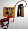
Well I made an PCB for it, built and tested. Circuit can be tuned to indicate continuity over an wide range. Below a few ohms or below a few kilo ohms. Calibration is done by adjusting the 25-turn precision trimmer. If to be used for detecting only dead shorts, connect alligator clips together and turn clockwise until the buzzer and LED comes on. It should be noted that the buzzer has its own internal driver circuit for oscillation / tone.
Interesting is that I simulated this continuity tester circuit in LTSpice and took and recorded many measurements. DC voltage measurements probing around the constant current source building block. But in the real world with an actual built, tested and working PCB prototype these measurements are different. The only thing I can think of is that I simulated with 2N2222 transistors but built the prototype with BC series BJTs.
You might want to ensure Voc does not exceed a diode drop unless you want this to tests LEDs too as the Voc is high enough to indicate forward conduction on diodes as a short, which would be part of your spec. if you tried to make one. However , the pot could be adjusted for <15 Ohms ESR to turn on 5mm LEDs but not trigger the comparator & buzzer.
The 1N4148 ESR @15mA would be comparable to the 5mm HB LED with ~ 15 Ohm ESR.
Test it on CMOS input to ground in both polarities to see what I mean.
However 15mA may exceed CMOS ESD current rating for diodes.
You might want to ensure Voc does not exceed a diode drop unless you want this to tests LEDs too as the Voc is high enough to indicate forward conduction on diodes as a short, which would be part of your spec.
I have not tried testing an diode yet. If it works would this be a positive or negative specification you think?
I do not think it will work since the circuit in essence measures the DC voltage drop across an constant current source, and this drop must be greater than the reference point, which is adjusted by VR1 (multi-turn precision pot) -- on the comparator for the LED and buzzer to be activated. The voltage drop across the CC for an dead short is very high. The higher value of resistance results in an lower drop. Now you can hopefully see why an diode will not register as an short.
The article provides all required entities to be able to reproduce the tester, but lacks circuit theory and step-by-step instructions on how to setup and use the device. I am more of an practical 'real world' hands on person in Excel, Photoshop, QuarkXpress, Protel, Circuit Maker 2000, MikroC, MS.net, Java and plus armed with the tools required to make single-sided PCBs, install parts taken from an comprehensive inventory and solder them up and test the board. But my communication skills are poor.
Lots of people here who are good writers on theory, so perhaps someone can add some circuit theory to it on the discussions tab of the article.
Yes I probably should do some factual specs. It will be, however though, inevitable for me to do some documentation besides pictures if I am going to sell this collection of 'simple' small board projects as DIY KITs in an shop...
Perhaps an paragraph on theory and the specs in dot-point form. To keep laser printing costs down if I can manage to one page it double-sided.
Perhaps some safety fine print about check for voltage before using.
Beware that probes will try to inject constant 15mA up to 3.5V + on Red clip., and that some Semi's like CMOS input ESD protection diodes might only be rated for 5 mA.(?)
The 5V reg is a bit of a waste.
With a bit more thought, it could be spec'd as an LED tester, logic probe , battery tester with minor additions.
Of course you could get away with using just two resistors to form an voltage divider... That 25-turn pot is there because this is an beginner's project, and when you first start out with electronics, from an kinetic sense you do -- you learn. The cost of that part is 28-cents to me. It stays!
Most people will purchase my low-end KITs for $9.99 because they are fun to build and educational. The practical use is all there too, but the emphasis of my selling point is all about advancing kinetic abilities with real world electronics. Now lets just experiment and see what happens if I give the pot 6-turns... You catch my drift right? Of course you do. You're no idiot...
Beware that probes will try to inject constant 15mA up to 3.5V + on Red clip., and that some Semi's like CMOS input ESD protection diodes might only be rated for 5 mA.(?)
This CC cct has 2 load lines controlled by 10K and 47R determined by Vbe of Q2 for the 47R and the 5V for the 10K load line.
It would have been more accurate to use the 78L05 as a CC source alone then current sense outside the loop on a series R set to <=100mV or so to a filtered comparator for indication. Buzzers are usually 0.25$ in volume including oscillator both piezo and magnetic.
It would also be possible to use a lower Vref and design off 2 AA's. Battery is your biggest cost driver.
I also have a DMM for $10 which I re-purposed for a $1k luminous intensity Goniometer with a bunch of Panasonic photo sensors and a rotary switch.
This CC is an textbook building block. The schematic has changed slightly. The shunt resistor in the CC is now 100R.
It would have been more accurate to use the 78L05 as a CC source alone then current sense outside the loop on a series R set to <=100mV or so to a filtered comparator for indication. Buzzers are usually 0.25$ in volume including oscillator both piezo and magnetic.
No honestly I think the biggest cost driver is going to be customers coming back to me and saying 'I think it is my poor soldering as to the reason as to why it will not work'
I know this is minor, but for the unused opamp, I like to pull the inputs to different potentials, just to ensure no ringing and you know the output state.
This site uses cookies to help personalise content, tailor your experience and to keep you logged in if you register.
By continuing to use this site, you are consenting to our use of cookies.


")
