Continue to Site

Welcome to our site!

Electro Tech is an online community (with over 170,000 members) who enjoy talking about and building electronic circuits, projects and gadgets. To participate you need to register. Registration is free. Click here to register now.

  • Welcome to our site! Electro Tech is an online community (with over 170,000 members) who enjoy talking about and building electronic circuits, projects and gadgets. To participate you need to register. Registration is free. Click here to register now.

Contactor Diagram

Status
Not open for further replies.

clive2016

Member
Hi

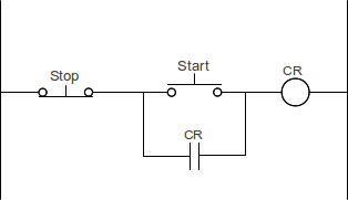
Can anyone help me out, I'm trying to work out how the live current of electricity flows in the contactor circuit as shown in my attachment which Iv'e indicated with red arrows.
ie when the miniture circuit breaker is close live flows through it to point 3 of the contactor and also to the normally closed red button which in turn will allow current to flow into green start button.
There are two other wires from the green start button, one of the goes terminal 5L3 of the contactor and the other goes to terminal 4 of the contactor.
If the green start button is normally open no current will flow through it to either 5L3 or 4 terminals of the contactor.

Could someone out there talk me through how the current flows from start to finish ie from the circuit breaker to the motor?

My thanks to anyone who can help me
Fig8 x.jpg

Fig8.jpg
 
There is a connection that's not very obvious in those diagrams, from L3 terminal (third along the upper side) to the contactor coil feed.

Operation-wise, you can think of it as there being two parts to the circuit.

The first is a standard "latching relay" circuit with the buttons, contactor coil and one contact.

Power feeds through the normally closed "stop" button to the start button and a relay (or contactor) contact.
The other side of of both the start button and contact connect to the relay coil.

When the start button is pressed, power is connected through to the coil and the contactor/relay pulls in - closing the contact across the start switch, so power stays on when the button is releases.

Pressing the stop switch disconnects power from the contact/coil and the contactor or relay drops out.

This shows a basic latching relay circuit, functionally the same as your diagrams; the circle represents the relay / contactor coil.

Latching-Relay-Circuit.png


The other part is the load circuit. That just switches power through separate contacts on the relay/contactor to whatever load is being operated.

[Edit - typo].
 
Last edited:
The contactor coil connections are the two at the top closer to the base than the connections to the four sets of contacts. The left hand side of the coil is connected to neutral. From the OFF state when the green NO button is pressed the right and coil connector is connected to live. (As the red NC button is closed.) As the contactor pulls in due to the coil being powered contact set 4 provide a path to live for the right hand connector for the coil so even when the green NO button is released the coil is still powered via contact set 4. When the the red NC button is pressed it breaks the live feed to the right hand connection to the coil so the contactor drops out. As both contact set 4 and the green NO button are open there is no path for the live to the right hand side of the coil when the red NC button is released so the contactor remains in the off state. Contact set 2 switches the neutral feed to the motor and contact set 3 switches the live feed to the motor.

Les.
 
Status
Not open for further replies.

Latest threads

New Articles From Microcontroller Tips

Back
Top