Continue to Site

Welcome to our site!

Electro Tech is an online community (with over 170,000 members) who enjoy talking about and building electronic circuits, projects and gadgets. To participate you need to register. Registration is free. Click here to register now.

  • Welcome to our site! Electro Tech is an online community (with over 170,000 members) who enjoy talking about and building electronic circuits, projects and gadgets. To participate you need to register. Registration is free. Click here to register now.

Constant Current buck/boost driver for LED / Supercapacitor

Status
Not open for further replies.

ACharnley

Member
Now that my dynamo USB project is reasonably mature I've moving onto something easier. The idea is to create something like this:

https://www.sjscycles.co.uk/lighting/0-busch-muller-toplight-line-small-rear-dynamo-light/

This device includes a supercapacitor but looses brightness at a standstill, decaying over 4 minutes. Probably it's just using resistors. I'd like to make an improvement by utilising a larger supercapacitor and a buck/boost circuit for efficiency.

Such chips seem to exist, although I haven't found the chip ID yet: https://www.aliexpress.com/item/5pc...ost-Buck-Low-Noise-Regulated/32365767349.html

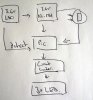
The topology will be;

5.25v reg -> 5.5v supercapacitor ->buck/boost -> 3x red piranha led, 2.1v (variable) 0.07A current (constant until impossible)

That chip works down to 0.7v but gives out 3.3v, but perhaps it or a similar model can offer the low voltage support and a constant current mode.

The efficiency probably wouldn't be much higher, it's only 70mA after all, but it would allow usage of the 0.7v-2.1v range of the supercapacitor.

Any thoughts?
 
Why use a capacitor to store a charge when the voltage of a discharging capacitor drops quickly at the beginning? Why not use a Ni-MH or Li-Po battery instead where the voltage of it discharging stays fairly constant?
 
It's a good question and here's my thoughts;

1. assuming the battery is dead it will take a while to gain any charge. In Germany the law states a dynamo light must have 4 minutes of backup power after only a very short amount of cycling.
2. li-ion batteries degrade after 500 cycles and chances are the unit will be sealed.
3. ni-mh is possible to extend life but takes longer to take in charge (1). It could work though, as I could use a timer instead and trickle charge to maximise life.
 
Trickle charging a Ni-MH battery shortens its life and is not needed with modern Ni-MH batteries that hold a charge for 1 year.
 
The dynamo can output almost any voltage from 0 to 6V. (??)
The super capacitor is rated for 3.3 or 5.5V
The LEDs are 2.1V at 70mA, x3 = 2.1V at 210mA or 6.3V at 70mA

What is important?
Cost? Complexity? Run time? Efficiency?
LED on all the time or flash.
Is it ok for the flashing to get slower to save power. (lower duty cycle) When the capacitor is low.
 
The dynamo can output almost any voltage from 0 to 6V. (??) - yes
The super capacitor is rated for 3.3 or 5.5V - either (5.5 is two in series). - nominal is 2.7v.
The LEDs are 2.1V at 70mA, x3 = 2.1V at 210mA or 6.3V at 70mA. - 2.1v @ 23mA each

What is important?
Cost? Complexity? Run time? Efficiency? Runtime -> efficiency ->complexity ->cost
LED on all the time or flash. -> on all the time (illegal to flash in Germany)
Is it ok for the flashing to get slower to save power. (lower duty cycle) When the capacitor is low. -I'd thought about pulsing the LED at say 10Hz (a very slight flicker) but don't know if it would really save much.
 
If you had a low capacity LiIon battery it would take less time to charge.

You can radically increase the life of a LiIon battery by using a conservative charge/discharge regime, say charge to 3.9V and discharge to no less than 3.1V. As long as you limit the charge current to a reasonable level all you need to do to charge a LiIon battery is to slap 3.9V across it.

The beauty of a battery is that it will provide power immediately without the need for any charging. It will also provide power when the bicycle is stationary- waiting at a junction for example.

spec
 
Last edited:
A battery voltage remains fairly constant during a discharge, unlike the voltage from a capacitor that drops quickly and a lot the moment it begins discharging.
 
I've attached an image with my thoughts. A PIC is used to;

1. if a signal from the dynamo is detected a 4 minute counter begins. Each signal resets it. If it reaches 4 minutes it enters sleep and watchdog monitors the pin.
2. if awake, an LDR on the comparator pin, plus a hysteresis buffer decides if it's dark.
3. if dark, power is supplied to a current limiter to the 3 LED's.

The part I'm unsure about is charging and drawing power from the battery at the same time. I think this would be more complex using a LI-ion (discharge protection, can't draw at same time as charge), whereas I could slow charge a Ni-Mh to a voltage a bit less than it's total capacity using a resistor (no need to make it more complex I think). Alternatively the PIC could have a capacitor across it's power input and if it doesn't detect power from the LDO then it switches on an output which enables a transistor which bridges the battery to the pic.
 

Attachments

  • DSC01550.JPG
    DSC01550.JPG
    196.4 KB · Views: 155
I suspect you're GREATLY over-thinking this, and making it far more complicated than it needs to be.

You don't 'draw current at the same time as charging', just as with a car alternator/battery as you draw current it takes it directly from the charging source, and only takes from the battery if there's not enough from the charging source.

However, as LI-ion is more complicated, and easily prone to damage (or bursting into flames :D) - then it makes sense to use NiMh, or even NiCd.
 
Hi Nigel, re: power source, that was my thinking with Nimh/nicd. With li-ion it's not as simple as there must be discharge protection or the cell is damaged (<3.4v or something).

The rest of the spec is a bit more complicated but solves the issues with the current products;

1. it doesn't dim when the rider stops (as the supercapacitor does)
2. comes on automatically when it's end of day/ dark
 
I suspect you're GREATLY over-thinking this, and making it far more complicated than it needs to be.

You don't 'draw current at the same time as charging', just as with a car alternator/battery as you draw current it takes it directly from the charging source, and only takes from the battery if there's not enough from the charging source.

However, as LI-ion is more complicated, and easily prone to damage (or bursting into flames :D) - then it makes sense to use NiMh, or even NiCd.

LiIon is simple to charge and all the talk about exploding etc is overdone. LiIon is better in all respects than NiCad and NMH.
(1) Lower volume
(2) Much lighter (NiCad is extremely heavy)
(3) Better charge retention than NiCad and NMH
(4) Simple to charge, especially if a conservative voltage range is used to greatly extend battery life. (NMH is particularly difficult to charge because of the low and variable -dV)
(5) Higher terminal voltage (3.6V as opposed to 1.3V)
(6) No need to cycle to keep in condition (NiCad can be difficult and also NMH can act strangely)
(8) Non toxic (NiCad is extremely toxic)

That is why LiIon is used exclusively in most modern equipment; mobile phones, cameras, laptops, puffers, electric vehicles. Even battery power tools are increasingly moving over to LiIon.

spec

'The Li ion charger is a voltage-limiting device that has similarities to the lead acid system.'
**broken link removed**
 
Last edited:
Hi Nigel, re: power source, that was my thinking with Nimh/nicd. With li-ion it's not as simple as there must be discharge protection or the cell is damaged (<3.4v or something).

The rest of the spec is a bit more complicated but solves the issues with the current products;

1. it doesn't dim when the rider stops (as the supercapacitor does)
2. comes on automatically when it's end of day/ dark
Discharging any battery below a certain voltage will damage it. The lower limit for LiIon is more like 2.6V rather than 3.4V

spec
 
Nicad/Nimh would only discharge to the PIC's lowest operating voltage (2v). I still can't see how Li-ion can be used without using the PIC to switch power source. It can't be put in parallel with the li-ion. Weight is a non-issue, even ni-mh 20mA 1.2 batteries are tiny.
 
Nicad/Nimh would only discharge to the PIC's lowest operating voltage (2v). I still can't see how Li-ion can be used without using the PIC to switch power source. It can't be put in parallel with the li-ion. Weight is a non-issue, even ni-mh 20mA 1.2 batteries are tiny.
Not quite sure what you are saying here. Any battery will discharge to zero volts. In fact if you discharge a NicCad battery too far, not only will the battery be damaged but the battery terminal voltage may reverse.

I suggested in a previous post to run a LiIon battery between roughly 3V and 4V; that voltage will be ideal for the PIC MCU, or have I miss understood what you are saying. :wideyed:

spec
 
By the way, if you are developing a product for world distribution, I would advise checking on the suitability of any item that contains cadmium. I not going going to start investigating safety standards and international regulations for you, but I vaguely seem to remember that NiCad batteries are banned or are about to be banned in certain countries.

spec
 
No, but if the li-ion was just in parallel with the pic it would discharge to 2v. It would need disconnecting circuitry like this;

https://www.aliexpress.com/item/5-p...arger-Module-With-Protection/32402397769.html

I don't think you can get voltage out at the same time (also known as passthrough)

Why 2V? Battery cut off circuits are pretty standard. I designed one on ETO recently: https://www.electro-tech-online.com/threads/cut-off-voltage-lithium-battery.147987/ Yes, you can take power all the time until the cut off voltage is reached. As the PIC will be taking a very low current, I imagine a very simple circuit would stop a LiIon battery from discharging below a specified voltage.

spec
 
Last edited:
2v is the PIC cut off voltage. After that it won't work (so shouldn't discharge the battery any further). I now agree if the li-ion isn't charged to it's max then it's easier to charge, straight voltage across it.

For the UVLO, a darlington and a zener to the base should do it, I think. That'll leave 3v to the PIC, which would give 2.4v at the output pin, which is acceptable (just!) as a 2v LDO exists with a 0.23v dropout. (LED's are 2v rated)

**broken link removed**
 
Last edited:
Correction, the 0.23v dropout gives very little room for li-ion discharge. Assuming the li-ion is charged to 3.6v that would give 3.43v before the LDO couldn't keep up and the LED's would dim.

Which may work, they're only on for 4 minutes and the battery would quickly recharge.
 
Last edited:
Status
Not open for further replies.

Latest threads

New Articles From Microcontroller Tips

Back
Top