Continue to Site

Welcome to our site!

Electro Tech is an online community (with over 170,000 members) who enjoy talking about and building electronic circuits, projects and gadgets. To participate you need to register. Registration is free. Click here to register now.

  • Welcome to our site! Electro Tech is an online community (with over 170,000 members) who enjoy talking about and building electronic circuits, projects and gadgets. To participate you need to register. Registration is free. Click here to register now.

Connector pins diagram.

Status
Not open for further replies.

jporras1

New Member
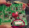
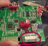
I retrieved this amplifier board from an Ion Plunge bluetooth speaker. I have no idea where I would connect the ground and power(vcc?). I am not that electronically minded when it comes to figuring out where to connect what. I do know that a the usb micro cable connected to this to charge the batteries. i have tried looking for help but haven't the slightest clue what to look for or where to look. Any help would be greatly appreciated.
 

Attachments

  • photostudio_1555607753510.jpg
    photostudio_1555607753510.jpg
    1.7 MB · Views: 191
read data sheet for this chip to find vcc and gnd. use a dmm set on continuity/resistance and touch the pins till you 0.00-0.02'ish or a beep.
 

Attachments

  • photostudio_1555607753510.jpg
    photostudio_1555607753510.jpg
    1.8 MB · Views: 187
why not use the battery connectors for power and ground? you need any controls/buttons that were in the speaker in order to control the board. exactly what was connected to the connector circled in red?

disassembly tip: freeze mist (or a "canned air" can turned upside down) will make the red glue on the connectors brittle, making unplugging the connectors much easier. just drip the liquid onto the red glue so that it gets very cold. this makes the plastic connectors brittle too, but far less brittle than the red glue
 
Status
Not open for further replies.

Latest threads

New Articles From Microcontroller Tips

Back
Top