Continue to Site

Welcome to our site!

Electro Tech is an online community (with over 170,000 members) who enjoy talking about and building electronic circuits, projects and gadgets. To participate you need to register. Registration is free. Click here to register now.

  • Welcome to our site! Electro Tech is an online community (with over 170,000 members) who enjoy talking about and building electronic circuits, projects and gadgets. To participate you need to register. Registration is free. Click here to register now.

Connection In Circuit ???

Status
Not open for further replies.

Electroenthusiast

Active Member
I have the idea and the circuit, all i want is to know how to connect Analog Part n Digital Part of the Following Circuit... I want to know how i can connect the 'bulb' circuit and the 'Digital XOR' circuit...
I Want the connections, will be happy if i get the ans with a Diagrammatic Representation.
It may be Simple, i'm a newbie and i'm on a project, so i want to use this in my circuit.
Pls>Thanks In Advance..:)

-------------------
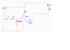
Below is the Circuit
 

Attachments

  • xor.JPG
    xor.JPG
    38.7 KB · Views: 159
Last edited:
how much voltage are the batteries?

if the bulbs are say 12v dc then simple transistor switches maybe.
an opti coupler may even be easier.
this all depends on bulb circuit voltage, current and what do you want to trigger the xor gates??
might be better to fully explain your design criteria (wants and desires the circuit is to do)
 
the circuit is a low current circuit....the bulb has a high resistance( several MΩ ) in series, therefor, current through it is low...
i'm using 9V/12V Battery for the Purpose...i may leave out the bulb if required, and sense the current >to make the Gate work.

I just want to know how can i run XOR gate Using the current in the Bulb Circuits?

hi,
If the lamp/bulb has a resistance meg ohms in series, then,
say it did measure 1 meg ohm, at 9V the current would be 9micro amps.
and the wattage 81uWatts.!!!
 
Last edited:
this might work??

its a way to input to TTL
needs to be reworked but I think this is what you want??
 

Attachments

  • ttl input.PNG
    ttl input.PNG
    19.4 KB · Views: 128
Status
Not open for further replies.

New Articles From Microcontroller Tips

Back
Top