Continue to Site

Welcome to our site!

Electro Tech is an online community (with over 170,000 members) who enjoy talking about and building electronic circuits, projects and gadgets. To participate you need to register. Registration is free. Click here to register now.

  • Welcome to our site! Electro Tech is an online community (with over 170,000 members) who enjoy talking about and building electronic circuits, projects and gadgets. To participate you need to register. Registration is free. Click here to register now.

Connecting two transistors "in series" (why does this not work)

Status
Not open for further replies.

Asheekay

Member
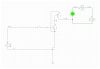
Here is the first circuit with only one transistor.

119480


Everything works as planned. The transistors provides a 100x current gain and the LED lightens up happily.

Now I wanted to lighten up the LED using even lesser trigger power, so I tried using two transistors and less trigger power.

119481


For reasons unknown (and probably lame) the LED doesn't lighten up at all and I'm not getting the 100x current gain.

What is that I am doing wrong?

JimB: Sorry if the circuits look confusing/misleading. I just got the screenshot of the software I use (EveryCircuit) and posted them as-is.
 
There's nothing right about that circuit, for a start 90mV isn't enough to turn the NPN transistor ON (why 90mV when you used 800mV before?), and there's no ground connection of any kind between the two circuits, and a total lack of the required resistors.

Personally I find these kinds of drawings and simulations less than helpful, and they seem to make little sense.

Hmm. The reason for reducing the power to the transistor further is that I want to know what is the least/minimum power at which I can lighten up the LED

1- How much (minimum) power should I use for the left transistor?

2- I did put a ground to the right side power source and it doesn't change anything.

3- I have put a resistor for the LED in the circuit but I didn't know I should put a resistor even between the transistors.

at the right transistor should be a PNP type transistor.

I changed the second transistor from NPN to PNP and ... it doesn't change anything.

Just how can I control the LED with such a small trigger power?

119483
 

Attachments

  • 1563528907257.png
    1563528907257.png
    73.1 KB · Views: 200
Last edited:
90 mV is too low a voltage to forward bias the base emitter junction the transistor which is required for the transistor to conduct between collector and emitter. If it is a silicon transistor it requires between 0.6 and 0.7 volts.

Les.
 
90 mV is too low a voltage to forward bias the base emitter junction the transistor which is required for the transistor to conduct between collector and emitter. If it is a silicon transistor it requires between 0.6 and 0.7 volts.

Les.
Thanks. Let me try with 0.7

Yes, the circuit does turn on at 0.7v, but somehow I am not getting any current gain at the collector nodes of the transistors, hence the LED isn't lighting up.

119484


Apparently, changing the trigger voltage with a current source of 100 micro Amps fixes all the problems.

119485


Now got to see if I can somehow amplify the 4.83 micro Amps up by 2.5 times ...

Any component that can do the job??
 
Last edited:
You have the collector and emitter reversed on the emitter follower stage. (I don't see why you need an emitter follower stage.) You would better off starting by telling us what you are trying to achieve rather than just showing a schematic. I have also now noticed that Nigel had already told you about the base emitter voltage in post #3 but you seemed to ignore the information.

Les.
 
I suspect your first problem is not understanding that transistors are current driven, and give current gain, a silicon transistor requires 'roughly' 0.7V across B and E to start conducting, so once you've reached that point its the current that matters. The usual sort of technique would be to have a resistor feeding the base, and a voltage feeding that - simple ohms law shows how the resistor converts the voltage in to a current.

You also can't just randomly connect transistors together, you almost always require one or more resistors, to both limit current, and convert voltages to current, and vice versa.

If you look at the sixth schematic on my hardware extras tutorial page, you will see an example:
 
With the symbols for bipolar transistors, the current movement follows the emitter arrow direction.

1. Please add reference designators to all components. It makes component-level discussions much easier on those trying to help.

2. If you follow the currents around the circuit, you will see that the LED current is trying to go through "the second" transistor backwards.

What does this tell you?

ak
 
Sorry if the circuits look confusing/misleading. I just got the screenshot of the software I use (EveryCircuit) and posted them as-is.

If you are thinking of continuing to expand your knowledge in electronics, either for hobby or profession, you should really learn a better software. Using the one you have now maybe easy to you but to anyone you ask questions of or want to explain things to it isn't/doesn't make much sense. There are many "free" ones out there that aren't much harder to learn, but follow the convention of established electronics.
 
You talk about minimizing power when you are wasting most of the 12V battery power in heat when lighting a 2V LED. Use a 3V battery instead in the circuit that has a 2V red LED.
The datasheets of all little transistors show that their saturation voltage loss is lowest when the base current is 1/10th the collector current. Current gains of about 100 are when the transistor is a linear amplifier, not a saturated switch.
 

Attachments

  • transistors driving LED.png
    transistors driving LED.png
    97.9 KB · Views: 203
Status
Not open for further replies.

Latest threads

New Articles From Microcontroller Tips

Back
Top