Continue to Site

Welcome to our site!

Electro Tech is an online community (with over 170,000 members) who enjoy talking about and building electronic circuits, projects and gadgets. To participate you need to register. Registration is free. Click here to register now.

  • Welcome to our site! Electro Tech is an online community (with over 170,000 members) who enjoy talking about and building electronic circuits, projects and gadgets. To participate you need to register. Registration is free. Click here to register now.

Connecting RST_N pin of microcontroller to another chip.

Status
Not open for further replies.

alphacat

New Member
Hey guys.

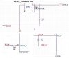
I've connected my microcontroller's (CC24300) RST_N pin to an active-low switch, so when I press the switch, it will HW reset the microcontroller.

The same switch also connected to a RST_N pin of a USB-to-UART chip, CP2102, so in that way both RST_N pins are connected, and both are connected together to the active lowswitch.

untitled-jpg.29465


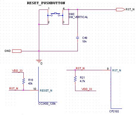
The problem that i'm facing is that every time I power-up the system, the MCU experiences a HW reset.

When I remove the CP2102 from the PCB, it doesnt happen.

Is it possible that the CP2102's RST_N pin is going LOW and then HIGH in each power-up of this device?

Further more, is it generally ok to connect two RST_N pins of two different devices to a single push button, or is it recommended to have each device its own reset button?
Thank you fellows.
 

Attachments

  • untitled.JPG
    untitled.JPG
    25.3 KB · Views: 950
Last edited:
Not familiar with that hardware - but do find the different value pull up resistors 43k and 4k7 surprising - is there a reason ?

The simplest way would be to use a minature double pole switch and keep both reset circuits separate.
 
dude you have R18 (43k) doing nothing at all though since there is a 4.7k there its using the 4.7k . Since its lower. Try placing it inline on the cc2430 like:

sdf-jpg.29467
 

Attachments

  • sdf.jpg
    sdf.jpg
    24 KB · Views: 720
Last edited:
Yes I know about that the 43K is redundant, thanks.
Thank you very much for your help.

1. Could you explain please about placing R18 the way you did?
2. Why should it prevent it from being toggled at power up?
3. Is it generally ok to connect two RST_N pins of two different devices to a single push button, or is it recommended to have each device its own reset button?

Thanks.
 
Last edited:
since you alread have a 4.7k resistor pulling the Line high its good enough for the CP2102 but i suspect the cc2430 requires less current on its line so you connect the reisistor to the reset line which is pulled up already. since you have a 4.7k its sending to much current to the "cc2430" so you have to limit the current to there.
 
Is it possible that the CP2102's RST_N pin is going LOW and then HIGH in each power-up of this device?

Yes. That's exactly what the datasheet says that it does:

RST pin9 D I/O Device Reset. Open-drain output of internal POR or VDD monitor.
An external source can initiate a system reset by driving this pin low
for at least 15 μs.
 
Last edited:
Status
Not open for further replies.

Latest threads

New Articles From Microcontroller Tips

Back
Top