Continue to Site

Welcome to our site!

Electro Tech is an online community (with over 170,000 members) who enjoy talking about and building electronic circuits, projects and gadgets. To participate you need to register. Registration is free. Click here to register now.

  • Welcome to our site! Electro Tech is an online community (with over 170,000 members) who enjoy talking about and building electronic circuits, projects and gadgets. To participate you need to register. Registration is free. Click here to register now.

Connecting PCB Terminal Block to LED Lead

Status
Not open for further replies.
Hello ETO,

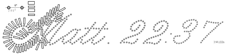
Working on a motion detector (PIR) actuated LED display
w 300 lights. Using 3 mm LED Mouser #: 604-WP710A10PGT
mounted in plexiglas operated by Maxim 7129 IC in
a custom designed PCB.

The question is how to connect the PCB to the LEDs.

At the PCB using Mouser 571_282834-8, TE Connectivity
Fixed terminal blocks. The terminal blocks
https://www.mouser.com/ProductDetai...cu6/tyhQV/GlIyync%2BR5zJOVGuWWFlMGm6TZ9uXIA==
while a bit expensive
work great because the connector screws down onto
the wire and provides good, firm connections.

The issue is the connection to the LEDs.

Have received :

Mouser #: 593-CNXBE4112
Mfr. #: CNX_B_E_4_1_12
Desc.: VCC Lighting Cables Lighting Cables 3MM PNL CNXBE4112
https://www.mouser.com/ProductDetai...Ikqup3QUmz/Q8k7gBr/4sqzV6M1gjuel%2B5IRrbvjg==
and
Mouser #: 523-SSL11J2LJ0B22A04
Mfr. #: SSL11-J2LJ0-B22A04
Desc.: Amphenol Lighting Cables Lighting Cables SSL1.1WIRE ASSY,WITH W2B LOCK
https://www.mouser.com/ProductDetai...a2WeR3g4GXWcnccVVD3Vb3JJEFGSvolicLooHaVVZ2WTA

Using the VCC CNXBX4112 it is often difficult to get the
LED leads to fit down into the header. See attached photo
marked 'LED One'.
[IMG]

In that photo the header marked 2.2.2 sits
down properly on the LED leads. The other two headers on the
right, like many others, even after fitting and refitting for
five or ten minutes will not go down onto the LED leads.

When the leads won't go all the way down on the LED lead,
if even touched slightly, will some times disconnect.

The wire coming out of the terminal block could be soldered to the
LED lead but that would be 600 solders. Will avoid if possible.

So purchased the Amphenol hoping to get an easier more, solid
connection at the LED, like the connx at the terminal blocks,
which are pretty easy, and very stable.
[IMG]

Hoped the Amphenol would solved the problem with fitting the header onto
the LED lead. But although the leads go into the header easier, the header
does not conduct through the LED to make the LED light.
See GIF marked LED Three.
[IMG]

Is there another lighting cable that would go from the
terminal blocks to the LED leads?
[IMG]

Thanks.

Allen Pitts, Dallas Texas
 
What is this? I think you made 7-segment displays by drilling holes in plexiglass.
119249
 
These Mouser 2 pin housings 571-280358 will work with these 571-182206-2 pins proving your wire guage is correct.. . You would also need a crimper.

It would take me a while to find a cheap crimper. "0.025" square pins" was a standard a long time ago.

Look up wire ferrule.
 
Let me introduce you to Tayda Electronics. Paying over $6 for terminal blocks is insane. A variety of types come in 2 terminal and 3 terminal sections that interlock together. You can build a block whatever length you need by adding sections together.

Tayda is in Thailand, with a US warehouse. Everything I have purchased from them has been good quality.

Screenshot_20190707-051623_Firefox.jpg


You might look at these Dupont cables for connecting the LEDs. These cables have single-position Dupont connectors on ribbon cable. As I recall, they made a decent connection to LED leads. If these could work for you, consider using pin headers on the circuit board rather than terminal blocks - then you can plug in these cables on each end.

SmartSelect_20190707-053817_Firefox.jpg


Personally, I hate making wired connections like you're doing. I'm lazy ;) You might consider circuit boards for each group of LEDs with an I2C or SPI driver chip on each board (or shift registers). Then the LEDs are soldered to a board so no loose connections, and the boards for each group can be daisy-chained together with as few as 4 wires between them
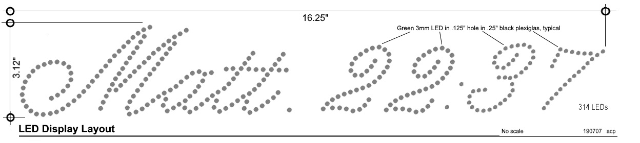
 
Hello Ron Simpson and KISS'

The display is not a seven segment display but rather a simple linear display of LEDs
This is partial animation: (wont let me add anim gif, have attached )


The overall display is about 3" tall and 16 " wide:
Matt_22_37_e_190707.jpg

Looked at the Mouser 2 pin housings 571-280358 and started to lay it out.

KISS, is this what you had in mind?
The rectangles are the Mouser 2 pin housings 571-280358 set on their side .


Matt_22_37_g_190707.jpg

Gonna be pretty tight.
Thanks for the ideas.

Allen in Dallas
 

Attachments

  • Matt_22_37_anim_150626.gif
    Matt_22_37_anim_150626.gif
    585.9 KB · Views: 196
You don't have to use the housings. You can use just the pins and some heat shrink. Use heat shrink on the pins.
For wire to make it easier, use split colored ribbon cable. Again, a piece of heat shrink so the ends don't split.

I tried very briefly to find a battery connector with pigtails.

Wire ferrules https://www.mouser.com/Connectors/T...1yzopyvZ1yzopxh&Keyword=wire+ferrules&FS=True are used so screws of terminals don't split stranded wire. You don;t need crimpers.

So, you can use any two adjacent colors from a ribbon cable just so, you can find the ends. Then use two colors for the ferules for the polarity.

Screw terminals with "wire protectors" seem to be elusive sometimes. It's a small piece of thin flat stock that crushes the wire and pushed by the screw.
 
Another option is to get your LEDs prewired.

**broken link removed**
 
Hello ETO forum,

The prewired LEDs is great idea. Unfortunately the LEDs are superglued into the Plexiglas. Will use on next project.

So I think Kiss is saying use the Panduit insulated ferrules. A heat shrink goes on the wire. The stripped wire goes into the ferrule and the LED lead goes into the other end of the ferrulle and then the wire end and LED lead are crimped together. Then pull the heat shrink down and heated to shrink for insulation. Right?
Will try.
Thanks for the input and excellent ideas.

Peace. Out.

Allen in Dallas
 
Not exactly.

Terminal Strip end

Get ferrules in two colors. They squish easily. No need to crimp. Use those two colors to identify positive and negative.
This 10 color ribbon cable can start with Black and white and white and grey. They can help distinguish the LEDs your wiring.
Get heat shrink that will go over the wire pair. Heat shrink (Clear) the insulated wire prior to the split. This keeps the wire from separating.

The ferrules go in the terminal blocks.
So, you have a pair of wires going to each terminal block that won't separate. Polarity identified by the color of the ferrule.

LED end.
Your pretty tight, so I thing housings are out of the question UNLESS you use one for grouping. e.g. every 10 LED's.
Get just the terminals for 0.025 inch square pins. I gave you one such pin. Get heat shrink that will shrink over just the pins and some insulation effectively making a single pin socket. Also get heat shrink that will keep the wires from splitting as above. Depending on the dimensions, you might be able to put them together. i.e. heat shrink the pins and then heat shrink the two pins together. Use different colors of heat shrink on the pins for polarity. maybe make the outer heat shrink clear.

Your real method should really be a printed circuit board and get your front panel laser cut. Seehttps://www.pololu.com/docs/0J24
If you decide to do acrylic mill the holes with a ball mill and/or an over/under reamer. Undersized reemers are for press fit and oversized is for a close slip fit.

If you did the artwork right the PCB and the LEDS should fit together nicely. You can use dishwasher liquid and a little water for a plastic lubercant,

Your artwork would then use a standard ribbon connectors or crimped pin Berg connectors to make all of the connections. The AMPMODU connectors would work. I don't trust IDC contacts carrying current.

These crimpers TE Connectivity/amp 696202-1 or Hozan P-707 or equivalent are not bad. I paid like $20.00 USD for the AMP tool. the prices now are ridiculous. or the TE tool, the pics are not correct many times. See the datasheet.

See: https://hackaday.com/2019/02/28/inside-the-secret-world-of-crimping/

I have one of the AMP tools.

Prices are still messy. e.g. **broken link removed**

They have crimps for the wire and crimps for the insulation on the tool.


This https://www.jameco.com/z/CNXCE2108-...LED-With-2-Pin-Locking-Header-5mm_143037.html or similar is what I was eluding too This is for a T1-3/4 LED, not a T1. So a connector might be less labor intensive.
 
Last edited:
Hello KISS and the ETO forum,

WOW!
Awesome answer. In fact so much knowledge assimilating it is daunting.

Had a project a couple of years back that required a lot of jumper cables so
bought cheapo crimper, wire, ferrules and Dupont housing and made a bunch of jumper cables.
Had so much trouble, crimping the ferrules, inserting them into housings,
keeping the ferrules in the housing and a half dozen other issues and points of failure
I gave up and purchased jumper cables, usually in ribbon strips.

That was my only experience with crimping.

The amount of info in
'Inside the Secret World of Crimping
and
'Common wire-to-board, wire-to-wire connectors, and crimp tools'
is amazing. Now trying to distill all this data and go to Mouser or DigiKey
and order a solution.

After reading for a couple of hours two approaches seem to appear.

1. Buy a kit like
Crimping Tool Kit, Preciva Dupont Ratcheting Crimper Plier Set with
1550pcs 2.54mm Dupont Connectors and 460pcs 2.54mm JST-XH Connectors for
AWG 26-18(0.1-1mm²)
This provides the crimp tool and the ferrules. Only other thing to buy would be the heat shrink.

or

2. Buy
YTH-202B for crimping on insulation
and
Engineer PA-09 for crimping wire

Only problem with this is still not sure which ferrule to purchase
from the huge array available.

Or get both and use the parts in the kit to see which ferrules work best.

Only thing to be sure can be eliminated are tools like
FCI HT-0095 RATCHET CRIMP TOOL $1808
or
Molex 63811-8700 $370
because my wife put me on the couch for a month.

Which crimp tool / ferrule would you use on 24 ga stranded
wire like that found in CNX_B_X_4_2_12 (Manufacturer VCC
Mouser part no 593-CNXBX4212) ?

Thanks.

Allen
 
I'll be back eventually. Don;t buy the precevia crimp tool. No good pics, but this https://www.amazon.co.uk/Preciva-AW...=2025&creative=165953&creativeASIN=B07H4LCNKT might be a good pic.

The crimp shown on the terminal is WRONG and incorrectly done. There appears to be no insulation crimp jaws on that tool.

The "wire crimp" folds the area inwards.

The "insulation crimp" is supposed to "roll" the metal around the insulation.

The pic in the link I posted clearly shows the insulation crimp biting into the insulation. It's not supposed to do that. I have not used a combination insulation/wire crimper that does both at the same time. Work and home has been with the AMP tool.

Have a read here: **broken link removed**

Usual types of problems. If the wire isn't gracefully crimped around the insulation, the terminal won't fit in the housing. That part should be round.

If the terminal is the wrong size for the wire, then you get an imperfect crimp where the strands are not attached.
 
Last edited:
This **broken link removed** has a better description and more drawings for the LED side of the VCC part.

It LOOKS like they use an "O-ring" on the base of the LED to secure the LED side. They call it a spacer.

The terminals look easy to remove from their housings.
 
I doubt it's possible to use Wire Wrap pins in your screw terminals and adjust so the housings fit? Your power and drive lines would also have to be adjacent.

Ferrules
Are essentially hollow tubes. Some are uninsulated and shaped like a funnel, so the wired can be inserted easiy. Otheres have a colored insulator at the end.
 
Eventually your caught with minimums. Sometimes you run into wierdness like won;t sell or talk to individuals.
This one company says business only. Well not strictly true. When I was working, I could order and pay with a credit card for myself and have the pre-paid invoice sent to me at a business address and it worked.

As a company we used them too. It was Teflon insulated pin plugs and sockets. In any event they offered one product gold plated and the other not gold plated. I think you had to order 100 or 250 to get them plated. We had no choice, we needed plating.
 
I for one forgot how simply KISS explains stuff. This man is a legend with thing's that need explaining so all can understand complicated stuff.

He is a legend. Keep It Simple Stupid.

Practical but with loads of theory backing it up. He knows stuff. And amazes me eveytime I stumble across one of his posts :)

tv
 
Here is the "thing"..... lots of theory actually means nothing... but putting theory into practice is a whole game changer. It takes a combination of practical and theory to make things work.

Jeepers, I'm clever tonight lol

tv
 
Me and wires....and wiring equals a big NOPE.

Nah. I can work it out.... but nope lol.

Life here depends on getting CRT sets repaired as quickly as possible.
 

Note the K36 pins. If the screw terminals were close together, these COULD attach to two adjacent pins.

We has this http://www.farnell.com/datasheets/2549918.pdf stuff at work. PTFE sleaving. It's rather hard and generally clear It could be used to insulate the LED leads at at least two levels, so the connectors don't get crowded. Dont get the shrinkable kind. it looks too expensive at 100 feet.
 
Status
Not open for further replies.

Latest threads

New Articles From Microcontroller Tips

Back
Top