Frisky2good,
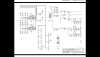
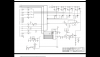
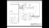
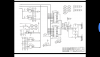
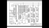
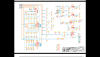
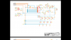
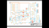
Your schematic "screenshots" are mostly unreadable on my PC, the resolution of the JPG files is a bit low.
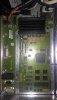
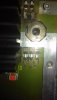
However, when I click on the original picture of the board, I can clearly see that the unknown components are adjacent to IC2, IC19, IC25 and IC30.
So if you can have a look at the schematics on your PC, and find those components, then post a higher resolution version of the appropriate schematic, then we may be able to decide on the nature of the unknown components.
JimB