Electro Tech is an online community (with over 170,000 members) who enjoy talking about and building electronic circuits, projects and gadgets. To participate you need to register. Registration is free. Click here to register now.
Welcome to our site! Electro Tech is an online community (with over 170,000 members) who enjoy talking about and building electronic circuits, projects and gadgets. To participate you need to register. Registration is free. Click here to register now.
While we're on this topic: Ive made a couple PCBs using the toner transfer method with what would be very nice results. The reason they are "would be" nice results is that I have to first print out my artwork on a regular piece of paper, then take that artwork and use a copying machine to print out onto photo paper. I cannot directly print onto photo paper because every time i try it with a laser printer, it always jams because the staples picture paper is not made for laser printers (its too thick). In this process of printing and then copying, the artwork gets rather jagged.
It works fine for my applications so far because I've never done SMD or anything reealy intricate.
Yeh, my school librarian isn't to happy about the problem of some kid jamming the photocopier every fortnight. (That kid is me). And its an industrial type as well
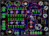
Is that a 6203 I see. I'm just starting on a motor control circuit with a L6203, a 16F819 and other bits to try and make a reasonably powerful (and cheap) servo. The hardware is now working fine and I'm just starting on the PID algorithm. If that is similar to what you have done, then I would be very interested in any pointers.
TIA
Mike.
P.S. This is what I have so far.
P.P.S. I didn't realise how bad my area looked.
They are RF type transistors, and rated to go to 300mhz, anything higher than that would probably be a mosfet. Dont know why you would use high speed transistors when a suitable cheaper transistor was available.
They are RF type transistors, and rated to go to 300mhz, anything higher than that would probably be a mosfet. Dont know why you would use high speed transistors when a suitable cheaper transistor was available.
Normal cheap silicon transistors commonly go to 300MHz, that isn't a spec for an RF transistor - just a cheap audio/switching transistor - the BC107 I commonly use is rated at 300MHz as well. As a handy byproduct, you can use them in bugs as well :lol:
This site uses cookies to help personalise content, tailor your experience and to keep you logged in if you register.
By continuing to use this site, you are consenting to our use of cookies.

")