Continue to Site

Welcome to our site!

Electro Tech is an online community (with over 170,000 members) who enjoy talking about and building electronic circuits, projects and gadgets. To participate you need to register. Registration is free. Click here to register now.

  • Welcome to our site! Electro Tech is an online community (with over 170,000 members) who enjoy talking about and building electronic circuits, projects and gadgets. To participate you need to register. Registration is free. Click here to register now.

Complete newbie needs help with LM3915 VU Meter Circuit

Status
Not open for further replies.

Muoshy

New Member
Just started with electronics a few days ago. I decided to build a microphone based VU meter using LM3915 and NE5532 for my first project.
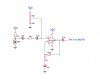
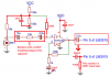
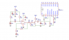
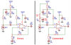
I wired the LM3915 according to the datasheet for a scale between 4.5 V and 7.5V together with some preamp schematic I found on Google.
I really should have learned the basics and done more research before continuing but I got really eager to start my first project and just went on with it.

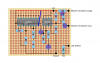
After soldering everything, I wired some LEDS to the circuit and powered it up with a 9V (9.9V) dc adapter . All of them lit up and there was no change despite me shouting into the electret mic. I checked the circuit with my multimeter and found that the 3rd pin of NE5532 had an input of 8.6V and the 4th pin of the LM3915 had an input of 5.7V. I'm not sure but according to what I´ve learned about voltage dividers, when R1 =R2 the voltage should be half of my VCC (9.9V).

Anyways, this was probably just one of the many problems my circuit had.
I appreciate any help you can provide!

Thanks!
 

Attachments

  • failed vu meter.png
    failed vu meter.png
    116.6 KB · Views: 635
Welcome to ETO!
some preamp schematic I found on Google.
Can you post the schematic? I think there may be a problem with the mic input. A schematic is easier to follow than a board layout. Some of the component values are unreadable on the layout.
 
Last edited:
Get rid of the 2.2uF, the 10k to its left and the 3.3uF and see if that helps. You might need to reverse the polarity of the 10uF so that it is correctly biased.
What you need, though, is a peak detector circuit (e.g. a simple half-wave rectifier based one) between the pre-amp output and pin 5 of the LM3915. Something like this.
 
Last edited:
1) Your wiring diagram does not show the mic connected to ground.
2) You did not calculate the values for capacitors, most are too big.
3) The two capacitors in series with the resistor between the mic and the opamp input should be replaced by a much lower value non-polarized capacitor.
4) The mic and opamp input must be biased from a filtered voltage, I added a filter. The Vcc also must be filtered with a capacitor that I added.
5) Your LEDs lit all the time because pin 5 of the LM3915 did not have a resistor to ground (0V).
6) Pin 4 of the LM3915 should be connected to ground for you to see different sound levels. With pin 4 at +4.5V then only loud levels will light all the LEDs. The difference in sound level between a peak of 4.5V and another peak at 6.1V is barely noticeable because they are both at almost the same sound level. The LM3915 shows a range of 30dB which is 1.414 times more input level (+3dB) from one LED to the next LED.
7) Without a peak detector circuit then the LEDs will show levels bouncing all over the place, frequently very dim.
 

Attachments

  • preamp for LM3915.png
    preamp for LM3915.png
    49.8 KB · Views: 322
Thanks! I'll redo my circuit according to your schematic. Hope I'm not being a bother but I have some (stupid) questions regarding the changes.
1) The capacitors at Vcc are there to stabilize the voltage, right?
2) Could I use a 100nF ceramic capacitor instead of a metallized plastic film one?
3) How do you choose appropiate capacitor values?
4) What is the purpose of the 220nF cap to 470k to ground, is it some kind of filter?

I do realize that I'm asking for a lot here and it would be extremely helpful if you could just tell me the technical terms for these things so I can look it up on my own.

Once again, thank you!
 
1) The audio signal might cause variations in a voltage that might cause electrical hum pickup or oscillation.
2) A ceramic capacitor generates a signal wqhen it is vibrated. Its signal can cancel or boost certain frequencies. Its value (capacitance) changes with voltage changes so a low frequency signal becomes distorted (but you do not hear a VU meter).
3) We can hear sounds down to 20Hz. the formula for a capacitor to pass frequencies down to a certain frequency is 1 divided by (2 x pi x R x f) where R is the resistance that the capacitor feeds and f is the certain frequency.
For example the capacitor between the mic and the 100k resistor I added at the input of the opamp: 1 divided by (2 x 3.142 x 100k x 20Hz)= 80nF, use 100nF.
4) The 220nF capacitor passes the AC audio signal to the input of the LM3915 and the 470k resistor connects the input pin 5 of the LM3915 to 0V. You want no LEDs to light when there is no audio signal then pin 5 must be at 0v. An input signal with a peak voltage of 6.1V will cause the LM3915 to light the 10th LED.
 
Will this work? I corrected the preamp according to your instructions and added a peak detector from the LM3915 datasheet. Not sure about the values on the peak detector though.
 

Attachments

  • vu-meter-v1 .png
    vu-meter-v1 .png
    136.2 KB · Views: 554
Remove R8 since you already have R7.
You show 5k for R10 but there is no such thing as a 5k resistor. With your 9V Vcc, the opamp output can swing a maximum of 6V peak-to-peak which is only 3V peak. Your resistors R9 and R10 make a reference voltage of +7.5V which is too high. The maximum output from the peak detector of 3V should cause the LM3915 to light the 10th LED then the reference voltage should be a little less than 3V. Your LEDs will not be bright because the values of R9 and R10 are too high. I would make R9 620 ohms and make R10 750 ohms. Then each LED will have a current of 20mA and the reference will be +2.76V.
 
I revised the resistor values, bought a breadboard and wired it up. It seems to be working without the peak detector although only very loud sounds light up the LEDs. Basically only claps light them up.
But when I remove R8 and pass the signal through the peak detector, it keeps the first five LEDs constantly lit. I used a BC557 for the peak detector.
Might be that I wired it incorrectly but I doubt since I've rewired several times and still get the same result. I'm not sure what the problem is.
 
I revised the resistor values, bought a breadboard and wired it up. It seems to be working without the peak detector although only very loud sounds light up the LEDs. Basically only claps light them up.
Sorry, I made a few errors that I have corrected here.

But when I remove R8 and pass the signal through the peak detector, it keeps the first five LEDs constantly lit.
Then R7 is missing.
 

Attachments

  • mic preamp corrected.png
    mic preamp corrected.png
    59 KB · Views: 328
Sorry, I made a few errors that I have corrected here.
Thanks, it works perfectly now.

Then R7 is missing.
R7 was not missing and I still can't get the peak detector to work properly but the VU meter seems to function somewhat well even without it. I'll probably skip it for now.

Thank you so very much for the help!

EDIT: It works when I add a capacitor between the peak detector and the lm3915, but although I get the desired effect it makes the LEDs somewhat unresponsive and flicker a bit. The droop rate is also affected by the capacitor I added.
 
Last edited:
Maybe your peak detector does not work because you have the pins on the European BC557 connected like an American transistor. The pins on an American transistor are EBC but on the BC557 are CBE.
With no signal, R13 connects the base of Q1 to 0V then its emitter is about +0.65V. The diode D1 has almost the same 0.65V but reduces its output voltage to the pin 5 input of the LM3915 back down to almost 0V.

Pin 5 of the LM3915 must be at 0V to turn off all the LEDs. R7 connects pin 5 to 0V but allows peak voltages from the peak detector to light some LEDs.
 
I have never used 1% tolerance resistors.
Maybe 40 or 50 years ago I bought modules made by National Semi with their LM3915 and a bar of LEDs. I joined two modules to make a 60dB range then I added an electret mic and preamp. Its LEDs faded away over the years.
12 years ago I designed and built a circuit using one LM3915 with a mic and preamp but I have it automatically add a gain of 20dB (10 times) when sound levels are low so it has a 50dB range. Its only adjustment is for brightness that I leave at maximum anyway.
 

Attachments

  • Sound Level Indicator schematic.PNG
    Sound Level Indicator schematic.PNG
    64.3 KB · Views: 261
Maybe your peak detector does not work because you have the pins on the European BC557 connected like an American transistor.
I did account for the layout difference.

With no signal, R13 connects the base of Q1 to 0V then its emitter is about +0.65V. The diode D1 has almost the same 0.65V but reduces its output voltage to the pin 5 input of the LM3915 back down to almost 0V.
Thanks for the explanation. I checked with my multimeter and found the problem. I only measured a 0.2V diode drop which left 0.5V to pin5. How should I reduce that to 0V? Add more diodes?
 
I did account for the layout difference.


Thanks for the explanation. I checked with my multimeter and found the problem. I only measured a 0.2V diode drop which left 0.5V to pin5. How should I reduce that to 0V? Add more diodes?
The diode is supposed to be a normal silicon diode like a 1N914 or 1N4148 that matches the base-emitter diode in a silicon transistor. Maybe you used an old germanium diode or a Schottky diode?
 
That's weird. I did use a 1N4148 diode. I've tested with several 1N4184s and all of them give a 0.2V drop. Maybe I recieved a faulty batch.
 
I got them from a local store, but the inner packaging hade some chinese letters on. I guess they came from China then.
 
Status
Not open for further replies.

Latest threads

New Articles From Microcontroller Tips

Back
Top