saiello
New Member
Hi All,
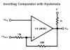
I've got a small project on the go and need some advice. It concerns the use of voltage comparators, in particular the LM311 and LM393. I've got a breadboarded ( plywood and cup screws!! ) test setup and I've managed to get both comparators to work including some hysteresis, but I am still having a problem in understanding why they won't switch around the reference voltage. The comparators are set up with single supply, +5V from a 7805 regulator and 0V ground as they are designed for. The reference voltage is to +ve input at 2.5V with about 0.1V hysteresis. I vary the input voltage to the -ve input using a cermet potentiometer. I expected the comparators to switch around 2.5V (allowing for hysteresis), but I am finding that they will only switch a full 0.5V below this value at around 2V. I've scoured the internet, tried all the example comparator circuits I can find but no joy. The datasheets are no help either. What am I doing wrong? My project involves use of more complicated IC's for which I can get working no problem, it's just that these pesky comparators won't play ball! Any help much appreciated, before I go completely nuts!
Thanks,
Salvatore