Hi,
This discussion is beginning to resemble a farce

! Please refer to the first line of post #9, which, for your convenience, is reproduced below:
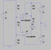
According to R5, R6 & R7, U2A output is high & U3b output low only when the voltage at U2a pin 4, V_in satisfies 6v < V_in < 7v (both bounding voltages w.r.t. ground).
Now, with reference to the original Problem 13 schematic posted by the OP, with TP1 = 0V, U1a's output will be 0V. You can vary R4 from 0 to infinity, but this would make not the slightest bit of difference to U1a's output of 0V. And since this output of 0V fails to satisfy the boundary condition of 6v < V_in < 7v, neither the LED in the opto, nor CR1, will turn on.
Just to ensure that this is indeed the case in reality, I
physically connected the joined inverting inputs of my
real live & practical (as opposed to simulated) test circuit (schematic loaded in post #21), to ground via a 20 Mohm resistance. As expected, the LED did
not turn on.
Hopefully this result will end this futile discussion once and for all (amen)

!

")
 ... that would have meant I had no need to do the time-consuming physical test. Anyways, I'm glad that we are all in agreement, even if it took a short detour and a slightly round-about way to get there in the end


