Continue to Site

Welcome to our site!

Electro Tech is an online community (with over 170,000 members) who enjoy talking about and building electronic circuits, projects and gadgets. To participate you need to register. Registration is free. Click here to register now.

  • Welcome to our site! Electro Tech is an online community (with over 170,000 members) who enjoy talking about and building electronic circuits, projects and gadgets. To participate you need to register. Registration is free. Click here to register now.

Common mode noise in offline power supplies

Status
Not open for further replies.

Flyback

Well-Known Member
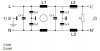
In offline power supplies, Common mode emissions are best dealt with by using common mode chokes in conjunction with Y capacitors.

However, do you agree that the “poor man’s” common mode noise reduction technique of using uncoupled inductors in both the live and neutral lines is also a somewhat worthy technique for mitigating common mode emissions? The idea is that the frequency of the noise in the live and neutral is reduced by the uncoupled inductances and goes below the 150khz level which is less penalised by EMC tests….so in other words, the overall common mode noise overall is not necessarily reduced in energy, but is reduced in frequency to levels where it is less penalised by the EMC regulations….do you agree with this “poor man’s” technique?

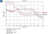
Also, when a company takes a product to an EMC test house for an investigation scan for conducted emissions….why do the test houses always present a “mixed” result graph with common mode and differential mode noise ‘lumped’ together into the same graph? It is , after all, very easy for them to use a splitter in the LISN and give separate graphs showing either differential mode emissions or common mode emissions on separate graphs……so why do the test houses not do this? A “Mixed” scan result graph, with common mode and differential mode levels “lumped” together is pretty useless, as the customer will not know whether common mode or differential mode filtering is needed and to what degree in each case.

Some EMC test houses actually give separate EMC conducted emissions result graphs with Live and Neutral lines shown on separate graphs. It is said that if the Live and Neutral graphs are the same then there are no common mode emissions, but this is not true…because if there are uncoupled inductances in both live and neutral then there could still be loads of common mode noise in there even if the live and neutral scan graphs look the same…do you agree?
 
But note that uncoupled inductors that can carry a high DC current level are much larger than a common-mode choke that can carry the same current, since the DC current cancels in a common-mode choke and doesn't saturate the core.
 
Do you agree that it is strange that the regulatory limits for conducted EMC into an offline power supply concern both common mode and differential mode emissions taken together?…in other words, your noise can be either all_common_mode, or all_differential_mode, or any mixture of the two, as long as the overall level is below the limit line. Why are there not limits for common mode and differential mode noise separately?

Another point is common mode emissions…..these are caused by very high frequency ringing in the range above above 30MHz……..Though 30MHz is above the actual maximum limit of the conducted EMC test. So the lay person would think that common mode emissions would not manifest themselves on the conducted emissions graph, but rather on the radiated emissions graph instead. However, this is not so, common mode conducted noise problems can and do occur right down to 150kHz. This is due to the fact that the mains bridge rectifier can result in the low frequency manifestation of the common mode noise…also, the effect of any differential mode inductors can push the common mode noise manifestation down to as low as 150kHz.
Do you agree?
 
A "X-cap" sits across the power line. It is large. Example 4.7uF. It will have some 50/60hz current.
The "Y-caps" sit from line(s) to ground. They must be small. Example 0.01uF. The 50/60hz current goes to ground. Ground current must be below 250uA, 750uA or 3.5mA depending on what you are building and where it will be used. (medical is very critical of ground current)

Diff-Inductors see the full load current. With out PFC the peak current is much higher than you might think. Example 100uH 10A.
Common mode transformers see very little current. CrutsChow points out the load current subtracts out. Example 10mH 100mA.
Note that Common mode transformers have both CM and DM inductance.

So you have two types of filters.
small l + LARGE C
AND
LARGE L + small c

The goal is to get the noise off the line(s). If you are trying to hear your radio.....it does not matter (much) if the noise is only on one line or two or both in/out of phase. The power line is a very large antenna.
 
Hello,

In the attached AC filter we can see that L1 is a common mode choke.

We are trying to reduce the component count of this filter. Do you agree that we can get away with omitting the Cy1 capacitors , but that we must keep the Cy2 capacitors?

In fact, why would the Cy1 capacitors be needed at all?.....i mean, any noise that has escaped out out to earth, would always want to take the least resistance path, and that would definitely be through the Cy2 capacitors….because then the noise would be going back through the common mode choke and thus would not see the high common mode impedance of the common mode choke.

So why are the Cy1 capacitors included? If anything the Cy1 capacitors should just be used as extra capacitors at the same position as the Cy2 capacitors. Do you agree?
 

Attachments

  • AC Mains filter.jpg
    AC Mains filter.jpg
    20.7 KB · Views: 151
As you know, Common mode noise returns to earth. (as you know, it obviously came in to the product via live or neutral)
If noise returns via the mains live or neutral than its not common mode noise. Any noise going through any of the y capacitors will end up returning via live or neutral, and so it will not be common mode noise.
True common mode noise, which returns to earth does not get “LC filtered”. Common mode noise couples out of the product, and then returns to earth, probably outside the product….it certainly does not traverse the y capacitors, because if it did, then it would be going back in to live or neutral, which means it would not be common mode noise any more.
Common mode noise is reduced by having a common mode choke…..the common mode choke “forces” noise which has coupled out of the product to come back into the live or neutral wires, via the common mode chokes other half……so it makes the noise into differential noise, which gets acted on by the differential filter.
So, Y capacitors do not filter common mode noise……Y capacitors actually transport noise back into the mains live or neutral from earth…..making it “differential mode noise”.

This is why I question why Cy1 (in schematic in post #5) is needed. Any noise which has coupled out of the product that will return back into live or neutral would choose the Cy2 route…because that takes it back through the other half of the common mode choke…where it sees the inductance of the common mode choke cancelled out…..if the noise were to return via Cy1, then it would miss out the other half of the common mode choke, and it would see a very high inductance, so therefore it would certainly not take that route…electricity generally takes the lowest impedance route, which in this case means returning back to mains via Cy2 and the other half of the common mode choke.
So why is Cy1 needed?
 
Continuing from my above comments on common mode noise……given the attached EMC scan result of a product which contains no AC mains filter, it is actually impossible to exactly calculate what combination of differential and common mode filtering will be needed to attenuate this noise down to below the pass/fail threshold.
The product of this scan is actually a 150W non-SMPS based lighting product……..but it does contain a 0.5W SMPS for bias power.
The only way you can approach this AC filter design (for the attached EMC scan result), is to make a Differential mode LC filter which attenuates by 35dB at 150kHz (that brings it below the line). You then have to more-or-less guess a common mode choke value, and guess accompanying Y capacitor values, and hope that that will convert most of the noise of the graph to differential mode noise….for which you can design a filter with known attenuation.
The problem with these conducted EMC scan result graphs, is that there is no way of knowing exactly how much of the noise shown is common mode and how much is differential mode.
It is thus impossible to exactly calculate filter components…you must simply design by emperical means (try it and see).
I have it on good authority that when returning to work this week, I will be sacked with immediate effect, due to my having first designed a pure diff mode only filter which attenuated down by 35dB at 150kHz. (but this did not solve it thereby I am due the sacking) The reason I did this initial pure diff mode design was because there is really not that much room for a common mode choke, so I needed to see how a pure diff mode only filter would perform. –Turns out that it doesn’t really attenuate much of what you see at all…which tells that most of the noise is actually common mode noise. If I was not going to be sacked, then I would put together a common mode/Diff Mode filter and try that out. However, the sack beckons, and I will be gone. Anyone fancy a job?
 

Attachments

  • Conducted EMC scan graph.jpg
    Conducted EMC scan graph.jpg
    82.3 KB · Views: 156
Do we all at least confess that it is not possible to actually calculate EMC filter component values for the above conducted EMC scan? (in post #7), ....since it contains a mixture of common mode and differential mode noise in unknown proportions.
 
This is related to the above..

Page 17 (RHS of page) of the following document…
**broken link removed**

….states the following about EMI filter design for offline power supplies….

Physical component layout becomes increasingly critical above
1 MHz. Improper layout can lead to increased capacitor ESL.
It is also possible for noise voltages or currents to couple around
the EMI filter directly into the mains.
….The wavelength at 1MHz is 300 metres, is it really the case that noise at around 1MHz could “couple around the EMI filter” and get straight back into the mains?
 
is it really the case that noise at around 1MHz could “couple around the EMI filter” and get straight back into the mains?
If you rout even a "data trace" through the filter you are adding xpF into the filter. (input to output) You might not care at 1mhz but at 300mhz it will really show up.

It is hard to see in the picture, but 3 of 4 transformers have "split bobbin" windings. These are common mode transformers. There are two windings. (1 for line, 1 for neutral) They are separated by a by a wall of insulation. They are so concerned about wire to wire capacitance inside the transformer that they wind 100 turns then there is a plastic wall then wind the next 100 turns. This greatly reduces the capacitance across the winding.
ac_line_filter_transformer_common_strong_style_color_b82220_mode_choke_strong_coil_inductor_with_ee_et_and_ft_strong_style_color_b.jpg
 
If you really want to see how to layout a filter:
Get a filter that comes in a metal can. Power connector on each end.
Open it up and see how the traces run. Look at how wide the traces are.
hero-product-master.jpg
 
Thankyou RonSimpson,
Our maximum conducted failure frequency is 5MHz, how important do you think layout is for that frequency and below?

The metal filters dont have internal damping which is bad for our product due to its "stair-step" mains current shape, which causes the undamped filter to ring..and upset the operation of our product..therefore we must design our own filter, and incorporate resistive damping eg across the inductors....also, most of the metal can filters strangely dont have a capacitor as there downstream-most component...which is essential for good operation of our product....also, we need wires (with stripped ends with ferrules) coming out of it for connection to our product, and most of the cans have spades on them, or screw terminals needing ring connectors, which is inconvenient for us.
 
Status
Not open for further replies.

Latest threads

New Articles From Microcontroller Tips

Back
Top