Hello.
The power supplies are transformerless basic power supplies. Because of the transformerless situation , i desided to post this thread here on high voltage section.
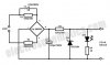
As i have said before the power supplies are transformerless. First one's output is 36Vdc and the second one's is 12Vdc. There is also ( one of them )scheme down below of thread (the other one has also same wiring diagram except fuse, which i added on high voltage section).
The goal was control 36Vdc with FET by 12Vdc gate voltage . Just a few minutes ago i tried to connect two power supplies 0V 's. And then ZZZZZZtttttt ,,, BOoooooomm...
The connection between 0V made by crocodile. After the "Boooooomm" the crocodile's wire burnt somewhere in it.
Im confusied cause, both circuit's has own glass fuse and they didnt blow up.. 12Vdc 's has 1Amps glass fuse and the other one has 8 Amps glass fuse.
Can someone tell why this situation may happen ?
The power supplies are transformerless basic power supplies. Because of the transformerless situation , i desided to post this thread here on high voltage section.
As i have said before the power supplies are transformerless. First one's output is 36Vdc and the second one's is 12Vdc. There is also ( one of them )scheme down below of thread (the other one has also same wiring diagram except fuse, which i added on high voltage section).
The goal was control 36Vdc with FET by 12Vdc gate voltage . Just a few minutes ago i tried to connect two power supplies 0V 's. And then ZZZZZZtttttt ,,, BOoooooomm...
The connection between 0V made by crocodile. After the "Boooooomm" the crocodile's wire burnt somewhere in it.
Im confusied cause, both circuit's has own glass fuse and they didnt blow up.. 12Vdc 's has 1Amps glass fuse and the other one has 8 Amps glass fuse.
Can someone tell why this situation may happen ?
Attachments
Last edited:
 . What a silly i am. I'm ashamed that I didn't notice of it......
