Continue to Site

Welcome to our site!

Electro Tech is an online community (with over 170,000 members) who enjoy talking about and building electronic circuits, projects and gadgets. To participate you need to register. Registration is free. Click here to register now.

  • Welcome to our site! Electro Tech is an online community (with over 170,000 members) who enjoy talking about and building electronic circuits, projects and gadgets. To participate you need to register. Registration is free. Click here to register now.

Common Anode Drive

Status
Not open for further replies.

Suraj143

Active Member
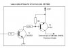
I'm driving 4 common anode LED segment digits.Attached is a one driver & I use 4 of these.I'm multiplexing them @ 100Hz.
Now I need to drive big segment digits like 1A per segment.Want to change the driving stage transistors.

What transistors more suitable & commonly available?
 

Attachments

  • RTC+Mod.JPG
    RTC+Mod.JPG
    21.3 KB · Views: 127
I need more information.
What is the 1A LED segment like? (part number)
Is there a resistor on each segment? (value)
What voltage on the LEDs?

You might look at the TIP32G transistor. At 1 amp collector current it will need 30mA base current. The 4.7k resistor will need to be more like 470 or 330 ohms to get the base current right. The voltage loss from collector to emitter is 0.2V. There will be 0.2 watts loss so the heat will not be too bad. The TIP32 is very common.

TIP125 Darlington is also good. Much higher gain so the 4.7k resistor is OK. The 10k resistor is inside the transistor. It will be hotter because it will have more voltage lost in the transistor. ( the collector to emitter voltage will be about 1.5V) So there is less voltage to go to the LED. There will be about 1.5 watts in the transistor so HOT.

Hi thanks for the information.

The segments are made by LEDs in series.I place 5 LED's in series for 12V. My 1st design uses 5 LED strips for each segment & now extend the strip count to 8 per segment to make large segments. Attached the drawing of what I making.

Common anodes driving from the above transistors & the segment digit cathodes drives through ULN2803 via 100R resistors. LEDs are 2V rated oval LED's.

I could parallel ULN2803 to make 1A of drain current, Now I need the source side (Anode drive side) adjustments.
 

Attachments

  • Seg A.JPG
    Seg A.JPG
    71 KB · Views: 113
Old design: LEDs=10 volts + 100 ohms = 1.0 volts (?) + transistor + ULN2803
The 100 ohm resistor controls the current flow.
The voltage drop for the LEDs changes with temperature and it changes for each batch of LEDs.

New design: You don't know what the voltage across the LEDs are. Look at the data sheet. Maybe 1.8 to 2.2 depending on when they are made. The ULN2803 drops 1.5 volts, depending on temperature. If you use the TIP125 transistor it will also drop 1.5V (more or less). You do not have a current limiting resistor. You don't know what the current is.

LEDs are not voltage devices. You should not but 2 volts across the LED. They are current devices so you should send 1A to the LED. You can think of a LED is much like a Zener diode. (2 volts +/- 20%)

I looked up some 1A red LEDs. Here is an example. If you put 2.85V on the LED you might get 1.0A but 2.95V=1.2A. A 0.1V change in the supply will change the current by 20%.

I looked at several types of LEDs. This one (2.85V) could be as low as 2.24 or as hi as 2.9V. Another part was labeled 2.1 min/2.45 typical/ 3.3 volt max. (you could get some of your LEDs at 2.85 and some at 2.25 volts. If you put 2.85V on a 2.25V LED you will probably get 2.1Amps. (and all this is not temperature stable)
upload_2017-5-18_6-26-8.png
 
Thank you very much for your help. TIP32 is a nice solution.You are right.The new segments doesn't have resisters I should put resisters to them.
 
Status
Not open for further replies.

Latest threads

New Articles From Microcontroller Tips

Back
Top