packet_loss
New Member
I'm not 100% sure where to put this thread, but I'm gonna try here first.
I'm building this lathe, mainly just to say I did. I've been a cnc programmer and tool and die maker for 18 years, so making a machine tool is a pretty natural inclination. However, this machine will never make a chip. I have worked in many shops where the owner let old manual machinery sit and rot even though they still work great. I've tried a thousand times to convince some of these people to let me turn the manual equipment into a full fledged, top notch CNC using fairly cheap stepper motors, driver boards and EMC Linux for the actual control. Not a single taker. I'm building this machine as a business card, more or less.
Since this machine will never actually cut anything I tried to get away with using small 5V motors to drive each axis, FAIL! Well, kinda fail? It was actually kinda of strange, what happened, I'm hoping you guys can shed some light. First, lemme show you a few pics, everybody likes project pr0n I hope.
Nice view from behind the spindle. That's the spindle on top and the Z axis stepper motor underneath. This was before the leadscrew was installed.
**broken link removed**
Underneath you get a fairly clear shot of the leadscrew and the nut that was eventually JB welded to the carriage base.
**broken link removed**
The 'new' stepper.
**broken link removed**
More pics **broken link removed** if you're interested.
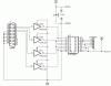
Alright, so here's a few details. The stepper motors were 5V 65Ω (part#LA82120-MI), these were being driven with an NTE2013. I should have looked closer at the specs for NTE2013 since I didn't catch the 12-24V for the voltage and my motors are rated 5V. I figured I would still test the circuit to make sure it worked since they never work for me anyway. I figured if it did work 12 was way more than 5, that just means it'll be stronger, I think. I just wont let it run but a hot second and it shouldn't burn anything up. So I do that and much to my amazement the circuit works! Well, kinda. Below is the schematic I used.
**broken link removed**
I have not built my cable yet for emc so I used the program and instructions found here. When I hit start the motor began to vibrate. I thought maybe it just could not turn the load so I hooked up another loose one I have. The output shaft is so small on the 5V motor that I couldn't really tell what is was doing exactly. At any rate it wasn't working properly and the most convenient thing to blame it on was having a 5V motor connected to a 12V supply, so I went and bought bigger motors. I was able to get three of these and a few other items for $11 at my local parts house. I have no idea what voltage these are rated for and to make things worse the color coded wires are different than the schematic and my other motors. These have brown, yellow, blue, red then two whites. I did my best guessing job and started it up, same thing, vibration. The output shafts on these are a 1/4", so I could see what was going on with these, they were going back and forth one step, thats why they seemed to be vibrating only. I am assuming the small motor was doing this too but I just couldn't see it or feel it. Since the colors don't match my schematic and I have no idea how to reconcile that I can't help but think I hooked both motors up wrong and that's my whole problem.
Well, if that wasn't too much of a painful read and you're still with me I'd love some help on how to translate these colors. Thanks in advance for any help you guys can give me!
I'm building this lathe, mainly just to say I did. I've been a cnc programmer and tool and die maker for 18 years, so making a machine tool is a pretty natural inclination. However, this machine will never make a chip. I have worked in many shops where the owner let old manual machinery sit and rot even though they still work great. I've tried a thousand times to convince some of these people to let me turn the manual equipment into a full fledged, top notch CNC using fairly cheap stepper motors, driver boards and EMC Linux for the actual control. Not a single taker. I'm building this machine as a business card, more or less.
Since this machine will never actually cut anything I tried to get away with using small 5V motors to drive each axis, FAIL! Well, kinda fail? It was actually kinda of strange, what happened, I'm hoping you guys can shed some light. First, lemme show you a few pics, everybody likes project pr0n I hope.
Nice view from behind the spindle. That's the spindle on top and the Z axis stepper motor underneath. This was before the leadscrew was installed.
**broken link removed**
Underneath you get a fairly clear shot of the leadscrew and the nut that was eventually JB welded to the carriage base.
**broken link removed**
The 'new' stepper.
**broken link removed**
More pics **broken link removed** if you're interested.
Alright, so here's a few details. The stepper motors were 5V 65Ω (part#LA82120-MI), these were being driven with an NTE2013. I should have looked closer at the specs for NTE2013 since I didn't catch the 12-24V for the voltage and my motors are rated 5V. I figured I would still test the circuit to make sure it worked since they never work for me anyway. I figured if it did work 12 was way more than 5, that just means it'll be stronger, I think. I just wont let it run but a hot second and it shouldn't burn anything up. So I do that and much to my amazement the circuit works! Well, kinda. Below is the schematic I used.
**broken link removed**
I have not built my cable yet for emc so I used the program and instructions found here. When I hit start the motor began to vibrate. I thought maybe it just could not turn the load so I hooked up another loose one I have. The output shaft is so small on the 5V motor that I couldn't really tell what is was doing exactly. At any rate it wasn't working properly and the most convenient thing to blame it on was having a 5V motor connected to a 12V supply, so I went and bought bigger motors. I was able to get three of these and a few other items for $11 at my local parts house. I have no idea what voltage these are rated for and to make things worse the color coded wires are different than the schematic and my other motors. These have brown, yellow, blue, red then two whites. I did my best guessing job and started it up, same thing, vibration. The output shafts on these are a 1/4", so I could see what was going on with these, they were going back and forth one step, thats why they seemed to be vibrating only. I am assuming the small motor was doing this too but I just couldn't see it or feel it. Since the colors don't match my schematic and I have no idea how to reconcile that I can't help but think I hooked both motors up wrong and that's my whole problem.
Well, if that wasn't too much of a painful read and you're still with me I'd love some help on how to translate these colors. Thanks in advance for any help you guys can give me!
")