Roff
Well-Known Member
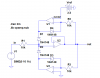
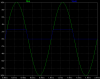
If anyone ever needs a precision clamp, here's one. The clamping error voltage is only limited by op amp offset voltages, since the diodes are inside feedback loops. It will have a tiny bit of overshoot, dependent on the slew rate of the input signal and the bandwidth of the op amps (assuming they are not slew rate limited). Shown below is a sim using behavioral 10MHz GBW, single-pole op amps, operating on a 1kHz, 20V p-p signal and limiting it to zero and 2.5V. The clip limits can of course be changed.
Sorry, SpeakerGuy.
Sorry, SpeakerGuy.
Attachments
Last edited:
