HI
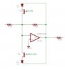
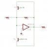
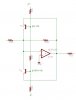
I have an op amp feeding the input of an ADC. this ADC must only have 0v to +2.5v on its input. So My Question is How do I clamp the output of the op amp to strictly and only 0 to +2.5 vlolts in order to protect the input of the ADC. The supply of the op amp is -12v and +12v and so far in my practical circuit the output of the Op amp seems to drift outside of these limits. (but that is another question)
can anyone help
thanks
david")
I have an op amp feeding the input of an ADC. this ADC must only have 0v to +2.5v on its input. So My Question is How do I clamp the output of the op amp to strictly and only 0 to +2.5 vlolts in order to protect the input of the ADC. The supply of the op amp is -12v and +12v and so far in my practical circuit the output of the Op amp seems to drift outside of these limits. (but that is another question)
can anyone help
thanks
david