Continue to Site

Welcome to our site!

Electro Tech is an online community (with over 170,000 members) who enjoy talking about and building electronic circuits, projects and gadgets. To participate you need to register. Registration is free. Click here to register now.

  • Welcome to our site! Electro Tech is an online community (with over 170,000 members) who enjoy talking about and building electronic circuits, projects and gadgets. To participate you need to register. Registration is free. Click here to register now.

Circuit Problem

Status
Not open for further replies.

GH Crash

New Member
I have a problem with a circuit I designed and I need your help in solving it.

First off, I'm definitely in the sub-hacker category when it comes to knowledge of IC and circuit. I can usually put a circuit together once someone gives me the component names and a basic circuit drawing. So, speak to me in small words otherwise you may loose me.


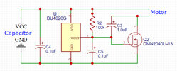
The LIC-P (my designation) circuit is designed to interrupt the current flow from a lithium ion capacitor, LIC or hybrid capacitor, to its load when the capacitor voltage drops to a certain point. Basically the circuit is a voltage detector IC that provides the gate signal to a n-channel MOSFET. The power supply is a LIC of between 10F and 100F capacitance rated for a minimum and max voltages of 2.3 and 4 volts respectively. The load is a small coreless DC motor rated at about 6 watts at 3.7 volts. The LIC-P circuit fits between the capacitor and motor. Attached is the circuit design and data sheets for the tow main components.

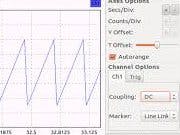
The problem is that the motor rpm varies in a cyclic manner with the circuit in place between the capacitor and the motor. The motor's rpm changes cyclically in a sine wave fashion from max rpm down to about 60% of max. The period of the oscillations is around a second and a half. The motor should run a constant full rpm until the capacitor's voltage drops below the set point of the voltage detector.

1. What is causing the motor rpm oscillations?
2. What do I need to do to the circuit to get the motor to run at a constant RPM consistent with the capacitor's voltage? (I realize that the rpm will gradually decrease as the capacitor's voltage drops.) What other information would be useful to solving this problem.


What other information would be useful to solving this problem?

George
 

Attachments

  • Circuit.jpg
    Circuit.jpg
    64.6 KB · Views: 219
  • bu48xxg_e-1874410.pdf
    1.2 MB · Views: 224
  • DMN2040U-1360765.pdf
    483.3 KB · Views: 201
Welcome to ETO!
If 2.3V is your chosen low voltage limit then you want the BU4823, not the BU4820.
1. What is causing the motor rpm oscillations?
The motor current is probably pulling the supply voltage down below the limit, so the FETgets switched off. This allows the circuit to recover (with some delay), so the FET is switched back on. Rinse and repeat.
 
The fix for motor caused supply drop is to make the power supply
more resilient to load changes. What does the LIC circuit look like ?
A cap in parallel with a lithium cell ? I think you need to look at supply
rail and make that have a lot less noise from motor load changes.

You could also have a poor ground system so the V detector is affected
by load dump into ground.

You could use a RC filter in power lead to Vdetector to remove transient noise
affecting its stability and clean switching.

Can you post a scope capture pic of the supply buss and the outpout of
Vdetector.

I would think about first trying a bulk tantalum polymer cap at Vdetector
supply pin. And if thats still a problem create additional isolation to load
changes with an L between Vdetector and motor. Use a scope to look at
your supply rail noise as you do these steps.

Leads in circuit must be short to minimize L effects.

Not sure why you have C3 there or C5. And the 100K I would think should be reduced
so MOSFET turn on is fast. That being said it could be the 100K and C5 are there to purposely
slow down MOSFET turn on to minimize transient demands and size of transients on supply
buss. The hysteresis in the Vdetector part is small so not much help here.


Regards, Dana.
 
Last edited:
alec-t, I did not state at what point I wanted the current flow interrupted. For the purpose of this trial circuit, I want the set point to be at two volts.

I'm sorry guys I don't buy the problem is tht the motor is pulling down the source. My reasoning behind that statement is that the motor never stops as if would if the motor pulled the capacitor voltage below its set point. The motor continues to run the entire time. only its rpm varies in a sine wave fashion, (You do know what a sine wave looks like, don't you?) not in a on-off fashion as would be normal if the motor was pulling the capacitor voltage down. The capacitor voltage follows a normal a discharge curve and only drops below the set point at the very end of a run. The capacitor I'm using is capable of providing 5 amps of current, the motor is drawing under a amp of current.

"tantalum polymer cap, Scope, L effects? You lost me Ta caps from VDD to where? No scope is available, Rail noise, what is a rail? Better yet can you indicate which rail(s) you are talking about the circuit drawing,

"What does the LIC circuit look like ?" I attached the LIC-P circuit to my first post. There is no LIC circuit. The LIC is a lithium ion hybrid capacitor. The LIC is indicated on the drawing by the word "Capacitor." Attached is a LIC datasheet. attached.

"poor ground system so the V detector is affected by load dump into ground." You lost me. What do you mean a poor ground system? Can you show me a spot in the circuit diagram of a poor ground system? And what is meant by load dump to ground? What load? What ground?

C3 and C5 were added at the recommendation of a knowledgeable electronics engineer. They were needed to filter out circuit noise.

If I remember right, R2 was added to prevent the Vout circuit from floating when off.
 

Attachments

  • Cornell_Dubilier_VMF306M3R8-30F-3.8v.pdf
    310.8 KB · Views: 229
"tantalum polymer cap, Scope, L effects? You lost me Ta caps from VDD to where? No scope is available, Rail noise, what is a rail? Better yet can you indicate which rail(s) you are talking about the circuit drawing,

Tant polymer instead of a electrolytic or a regular tantalum capacitor. For this reason (its ESR very low) :

1659991664267.png


Place cap from Vdd to ground.

"Scopoe L effects", using a scope to look for excessive transients that could damage other
components, specifically the MOSFET or the Vdetector....

Rail is the supply buss, like Vdd of Vcc as standard nomenclature.

Rail under discussion is power supply connection, eg. "rail" to Vdetector/motor.

"poor ground system so the V detector is affected by load dump into ground." You lost me. What do you mean a poor ground system? Can you show me a spot in the circuit diagram of a poor ground system? And what is meant by load dump to ground? What load? What ground?

Motor current is supplied by buss and fed thru MOSFET into ground, thats load dump.

Load is the motor.

Ground is your ground, as shown on your schematic labeled GND.

A poor ground system is where, typically, an analog components power is connected and that ground
then goes to other components for ground and loads, like motor. Daisey chained. Versus analog
components ground trace goes all the way, in a separate trace to board edge where ground meets
the board. Same for motor ground. That way the analog component does not see the IR drop due to
motor current until they meet.


Your LIC has fairly high ESR, so a low ESR cap to ground might help in parallel to LIC, physically close to
motor leads.

Advise you get/rent/borrow a scope if you are designing electronic circuits with mixed signal in them.

Post a pic of your prototype so we can see how its wired/routed.

R2 turns on the mosfet by charging its gate C when the Vdetector output is off.

I'm sorry guys I don't buy the problem is tht the motor is pulling down the source.

How do you know that w/o observing with a scope ?


Regards, Dana.
 
Last edited:
What is the period of the speed variation that you're seeing on the motor RPM?
 
You asked how I knew that the motor the motor wasn't pulling down the source. I don't know for sure. But I don't think what I have observed supports that idea. First, there is no motor speed oscillations when the cap and motor are connected directly together. Second, the speed oscillations are present regardless of the power source or the load. changing to a capacitor with higher capacitance or to a bench top power supply ans well as changing to a motor that draws less current does not eliminate the cyclic speed. I am trying to find someone with a scope that will take a look at the circuit just so we will know for sure.
Thanks guys for ideas and suggestion, I'm still having the problem and still trying to figure out what is going on.
 
These might help -


This is soundcard solution, scope + spectrum analyzer + sig gen, make sure you protect soundcard inputs -


Google "protect soundcard inputs"


Regards, Dana.
 
Thanks for link to the Soundcard Scope. Have you used the Soundcard Scope? How do you scope electrical signals using it? I browsed the manual and it appeared that you could but I missed the part where it said how to do electrical signals.

Would you explain your highlighting of the protect sound card statement? Evidently it is important but I don't know what to protect the soundcard from r how to go about it.
 
Onas approach - https://www.instructables.com/0-to-500v-Sound-Card-Osciloscope-and-probes-Cost-P/

Another - https://www.edaboard.com/threads/bu...lloscope-probe-and-sound-card-line-in.259543/


Sound card has limits on input V so you have to protect against over voltage, and
make a probe with a V divider to limit input V.

Some folks nervous, about using sound card inputs, eg. blowing them up.
Some users have purchased separate sound card (they are cheap) so if they
over V the inputs they can toss the card and add another.

You can google "protect sound card inputs", various circuits out there.

I have used sound card inputs in LV circuits and/or built V dividers to worst case
insure inputs are not stressed. LV Zeners are good for that.

Take the time to investigate/read the various solutions online and then proceed.

The one problem is no DC coupling. So I would direct folks to the Arduino like
PC projects I linked in earlier post. Cheap, Arduino card ~ $5 US. So keep in mind
you build two pieces, the probe / attenuator / protection circuit, and then
feed that to Arduino. Look for one that has a function generator as well as FFT,
super useful.


Regards, Dana.
 
Someone suggested that hysteresis, or lack thereof, was the cause of the problem. That a better approach would be to use one of the ICs designed for lithium battery protection. I think that I will try that approach.
 
alec-t, I did not state at what point I wanted the current flow interrupted. For the purpose of this trial circuit, I want the set point to be at two volts.
But that conflicts with the rated minimum voltage of the capacitor.
You said "The power supply is a LIC of between 10F and 100F capacitance rated for a minimum and max voltages of 2.3 and 4 volts respectively."
 
Note that the rated Absolute Maximum current that the open-drain output of the detector IC can sink is 70mA. In the absence of a gate resistor it is likely that this will be briefly exceeded when the gate capacitance of the MOSFET discharges. If the IC has built-in self protection, the excessive current may trigger the IC to shut down temporarily/intermittently, slowing the motor.
 
But that conflicts with the rated minimum voltage of the capacitor.
You said "The power supply is a LIC of between 10F and 100F capacitance rated for a minimum and max voltages of 2.3 and 4 volts respectively."
Yes that min capacitor voltage conflicts with the 2v output. Remember that this is an experimental circuit. Dropping capacitor below its minimum rating seems to have little/no effect on the capacitor if the capacitor is immediately charged to a voltage greater than is recommended minimum voltage.
 
Note that the rated Absolute Maximum current that the open-drain output of the detector IC can sink is 70mA. In the absence of a gate resistor it is likely that this will be briefly exceeded when the gate capacitance of the MOSFET discharges. If the IC has built-in self protection, the excessive current may trigger the IC to shut down temporarily/intermittently, slowing the motor.
This is good stuff, but maybe a little over my head.

"IC can sink is 70mA" What is the meaning of sink?

Are you suggesting that resistor be placed between the Vout of the IC and the gate of the MOSFET? What size resistor would you suggest?

Thanks for your help. George
 
What is the meaning of sink?
It means current flowing into the IC's Vout terminal to ground (when the internal FET switches on to pull Vout low).
If the voltage on the external FET gate and C5 is a maximum of 4V then a 100 Ohm resistor between Vout and the C5/R2/gate junction would limit the sink current to 40mA, i.e. well below the rated maximum.
There is no guarantee that this would fix your problem, but it's worth a try.
As Rjenkins asked (post #2), what is the effect of removing C3?
 
I agree with Rjenkins and Alec_t. Try removing C3. Curious if that might cause oscillations with the inductive load (motor). Also, might want to consider a flyback diode in parallel with your motor. Just a thought (it will prevent voltage spikes!).

I know you disagree with the idea of the motor pulling down the voltage, but it might be worth it to add a few bulk caps to provide a little extra energy when it's needed.

Per the datasheet, page 12, Operational Notes:
6)"...presence of strong magnetic field may cause IC to malfunction" How far away is this IC located relative to the motor?

7) VDD line impedance might cause oscillation because of the detection current

10) "....recommended value of RL..."
Looks like you went straight to a value of 100kOhms. Try starting at 10kOhms and change values up to 100kOhms. I'm curious if that would affect anything.


Also, read this for more on hysteresis: https://www.ti.com/lit/ug/tidu020a/tidu020a.pdf

Read app notes. They are super helpful! TI and many other companies write great application notes for design.

Best of luck!
 
1ohm.JPG

Maybe add a 1ohm resistor here. This may keep the detection voltage propped up enough. This is in reference to the datasheet operational notes, line 7). And at 1ohm you're not going to dissipate too much power.
 
Last edited:
Status
Not open for further replies.

Latest threads

New Articles From Microcontroller Tips

Back
Top