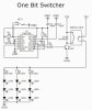
The circuit converts an SPDT pushbutton switch to alternate-action. U1A is a set-reset flipflop to debounce the switch, and U1B is a toggle flipflop that drives the output stage.
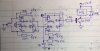
There is a problem with all of the Set and Reset inputs. This would be more apparent if you drew a schematic instead of a wiring diagram. A correct schematic has separate symbols for each flipflop with the inputs and outputs arranged in a traditional manner, not the physical package. This makes its possible for any experienced viewer to see the intent of the design. Redraw the schematic and you will see the problem. Yes, the circuit works, but not by design.
See figure 3 of this datasheet for the correct schematic symbols.
ak
ps. Ground symbols never point any direction but down. Antennae and power symbols point up; grounds point downward, always.