I am working on a project to interface a mouse and keyboard with an xbox 360 controller. I am still learning but I do understand PICs so much better after 2 weeks of learning. I believe I have figured out how to connect all of the buttons from the 360 controller to a PIC(lets assume I am using a PIC16F737) using 4x4066IC analog switches. So here are the questions that I have:
Thank you in advance for your replies, I am learning a ton from them.
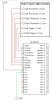
- Could someone please draw the schematic for connecting a PS/2 female port to a PIC16F737?
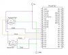
- I need to attach 6 analog signals (coming from potentiometers) to my PIC16F737. Do I need to attach reference voltages to the + or - Vref spots to be able to use th analog (DAC) pins?
- Since I am attaching 6 analog signals to my PIC do I need a different Vref connection for each of the 6 signals?
- What exactly is a Vref for?
- The best way for me to learn about the analog pings on PICs is if someone could please draw a schematic for connecting analog signals to the analog pins of a PIC16F737 with a little explanation.
Thank you in advance for your replies, I am learning a ton from them.