Electro Tech is an online community (with over 170,000 members) who enjoy talking about and building electronic circuits, projects and gadgets. To participate you need to register. Registration is free. Click here to register now.
Welcome to our site! Electro Tech is an online community (with over 170,000 members) who enjoy talking about and building electronic circuits, projects and gadgets. To participate you need to register. Registration is free. Click here to register now.
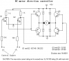
A high on input a, low on input b q1 conducts lowering voltage on it's collector which in turn causes q4 to conduct, meanwhile since there is a low on input b the collector of q2 is at a high level which causes q5 to conduct this gives a path from ground thru q5, the motor, and q4 to +9v. operation is mirrored using q3 & q6 if swap input levels. If both inputs are high then only the pnp transistors are biased for operation and no complete path for current to flow, if both inputs are low then only the npn transsitors are biased for operation and thus no complete path for current to flow.
Yea right. Vbe ≈ 0.6V aprox. And Vbe on both transistors is coupled in series. That means any supply voltage above ≈1.2V will short through emitter-base on each couple of transistors.
Yea right. Vbe ≈ 0.6V aprox. And Vbe on both transistors is coupled in series. That means any supply voltage above ≈1.2V will short through emitter-base on each couple of transistors.
Operating Q1 and Q2 in cutoff/saturation prevents shorting through. A pair of high-value resistors connected between the bases would ensure the current from the drivers at the tie point is sufficient to prevent short through. Better to replace the drive transistors ( Q1 & Q2 ) with IC invertors to reduce drive impeadance. Significant current would flow during transient, so that period must be short and low duty-cycle. If not the case, then an alternative layout is requried.
PS, never allow the inputs to the bridge to "float"
NOtice what MrAl wrote. If you swap the upper and lower transistor, it might work - or it progably will (if control circuit works). The circuit you posted here will sort of act like two set of two diodes in series in forward direction and therefore it will short.
Adding resistors between the bases of a pair of complementary transistors (Q3 - Q4) will not solve the problem. The transistors will connduct all the time (draw lot of current, but not shorting).
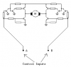
I draw a corrected version of the h-bridge that should work.
Adding resistors between the bases of a pair of complementary transistors (Q3 - Q4) will not solve the problem. The transistors will connduct all the time (draw lot of current, but not shorting).
Not true! Adding a pair of resistors between the bases of each pair of transistors and feeding the control current at the junctions of the reisitors solves the OP's circuit's issues.
Not true! Adding a pair of resistors between the bases of each pair of transistors and feeding the control current at the junctions of the reisitors solves the OP's circuit's issues.
We don't know how much power the motors will dissipate, so the transistors doesn't have to burn.
I draw another circuit that solves both issues. However it must consume some current even when the motors doesn't run.
Now I have posted two versions with their strength and weakness. In the first one, as Nigel stated, quite a bit power is lost due to the 1,2V loss over transistors. But on the other hand, it doesn't consume power when the motors doesn't run.
The latter one will consume some power when the motor doesn't run because voltage will always cause current to go through resistors that shall turn the PNP on.
They will get hot under most circumstances, particularly the top ones, as they are very poorly biased.
Now I have posted two versions with their strength and weakness. In the first one, as Nigel stated, quite a bit power is lost due to the 1,2V loss over transistors
It will lose considerably more than that due to the poor biasing of the top transistors - which aren't switched, but run as linear devices dissipating lot's of heat.
Here's a working design from a kit robot on another of my sites.
It's hardly any more complicated than your original (non-working) circuit, bear in mind it's two channels, plus a battery test circuit. It's fully, and excessively (because it was for beginners), described on my webpage.
100€ question: What happens if both inputs goes high? Shortcut.
This site uses cookies to help personalise content, tailor your experience and to keep you logged in if you register.
By continuing to use this site, you are consenting to our use of cookies.

")