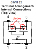
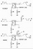
I hope someone will have an idea why this circuit is not working, I am tearing my hair out. I built it on a pc board and it worked, but I wanted to make changes, so I built a new pc board but did not change this circuit. The first circuit below is what is on the pc board. I took the solid state relay off the pc board and put it on a test board (2nd circuit) and it worked OK. I put the relay back on the pc board with the 1K resistor to simulate the test circuit, but it still does not work.
Continue to Site
")