Electro Tech is an online community (with over 170,000 members) who enjoy talking about and building electronic circuits, projects and gadgets. To participate you need to register. Registration is free. Click here to register now.
Welcome to our site! Electro Tech is an online community (with over 170,000 members) who enjoy talking about and building electronic circuits, projects and gadgets. To participate you need to register. Registration is free. Click here to register now.
What voltages are available to run the circuit?
What is the current range for the constant current source?
Can you post a schematic or sketch of the system you have so far?
What voltages are available to run the circuit?
What is the current range for the constant current source?
Can you post a schematic or sketch of the system you have so far?
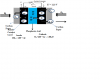
Sir I have a setup to test a small size fuel cell.In this hydrogen and oxygen are used as fuel.In the absence of fuel ,cell potential starts decreasing and if load (Current source) is connected to the cell then cell can damage.The OCV for this cell is 1 V (approx).But if by any means there is a starvation of fuel then cell voltage starts decreasing rapidly and if load (current sourse )is connected to the cell then cell can damage.It is seen that if cell voltage is above 450 mV then cell is safe but as soon as it goes below 450 mV then cell damage .To protect the cell in the absence of fuel this protection circuit is required by disconnecting the current source(Load) from cell.schematic is attached ..
Sir I have a setup to test a small size fuel cell.In this hydrogen and oxygen are used as fuel.In the absence of fuel ,cell potential starts decreasing and if load (Current source) is connected to the cell then cell can damage.The OCV for this cell is 1 V (approx).But if by any means there is a starvation of fuel then cell voltage starts decreasing rapidly and if load (current sourse )is connected to the cell then cell can damage.It is seen that if cell voltage is above 450 mV then cell is safe but as soon as it goes below 450 mV then cell damage .To protect the cell in the absence of fuel this protection circuit is required by disconnecting the current source(Load) from cell.schematic is attached ..
Given those voltage and current figures I think the most practical cut-out would be an automotive relay. That would need a 12V supply and a comparator circuit set to trigger at about 450mV, probably with a bit of hysteresis.
A voltage reference, such as a TL431, a comparator such as an LM339/393, a transistor such as a 2N2222, a diode such as a 1N4148, and a relay, should do what you want.
How dependent is the cell voltage on load current? Any comparator hysteresis involved would need to take this into account.
Once triggered, should the cut-out latch until manually reset? If not, under what conditions should reset occur?
It looks like the only source of power is the 1 to 0.45 volts from the cell. This makes most approaches not work. I think the voltage will collapse to zero for a short time. While the breaker is opening the voltage is between 0 and 0.45.
Please confirm that there is no other source of power.
If that's the case then the only suggestion I have would be to modify a solenoid valve of the type used in flame-failure sensors. That type has a very low resistance coil powered by a thermocouple, so that even a fraction of a Volt can drive an Amp or so through the coil to hold the valve open.
Here is a LED boost that can be modified for constant voltage not constant current. It works down to 0.50V.
I have used other parts that work lower but many are not in production now.
----edited----
The MCP1643 needs 0.65V to 0.8V to start. A unloaded cell will do that. Once started it will work down to 0.5. I think most worked to 0.45 if the load is light.
----edited----
Found boost PWM down to 0.1V but the price is 10X. "energy harvester"
This site uses cookies to help personalise content, tailor your experience and to keep you logged in if you register.
By continuing to use this site, you are consenting to our use of cookies.