Hi,
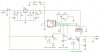
The attached image is my finished circuit, which i would like your views before sending off for PCB manufacture.
Please feel free to comment on the design.
Operation:
The input is +12V from a mains adaptor, the circuit must opperate when the mains fails becuase it is a timer/clock counter.
The input is fed into X1 and IC1 78L05 regulator provides a smoothed 5VDC supply for the PIC. A battery backup is provided via a 3V lithum battery, and the two supplies are mixed via 2 diodes, so when the 5V reg output turns off because of a power failure, the battery will power the circuit.
The PIC can opperate down to 2.2V so 3V battery - 0.7 diode = 2.3V = OK ?
Caps C1 and C4 are typical values, and are not calculated, so their values may be wrong? The supply is via a regulated DC adaptor.
Q2 provides a sence for the pic so the PIC knows if it is using batteries or the 12V adaptor. When this sence is activated (Q2 off, GP0 pulled high via internal pullup), the PIC does not enable the output transistor (PNP) Q3, and goes into low power mode.
Q3 basicly switches the adaptor supply to the output. I needed a low dropout at the output (X2 connector), so i used PNP. Is it connected correctly? Correct resistor values for R6/R9 ?
The LEDs just show the supply states, except LED3 which will flash when the PIC detected a brownout during battery operation. The flashing will start when the adaptor power is restored to indicate that the clock (implimented in software in the PIC) maybe incorrect and will need resetting.
SL1 connector allows for in-circuit programming of the PIC, which will use PIC ports GP0 and GP1. Because the programmer will place 5V on these lines (clock and data) i have added a 1k resistor (R4) to my pull-low circuit. Will this be OK?
Any remarks are greatfully welcome.
Joe
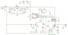