Continue to Site

Welcome to our site!

Electro Tech is an online community (with over 170,000 members) who enjoy talking about and building electronic circuits, projects and gadgets. To participate you need to register. Registration is free. Click here to register now.

  • Welcome to our site! Electro Tech is an online community (with over 170,000 members) who enjoy talking about and building electronic circuits, projects and gadgets. To participate you need to register. Registration is free. Click here to register now.
Status
Not open for further replies.

Clarkdale44

Member
Hello

As the title states, my ac only cheap clamp meter is reading dc currents when i am charging battery bank through an inverter...

My inverter is rated to charge 12v 150Ah battery at 16 amps and during charging when i put the clamp meter on the red battery charging cable, the meter shows 15.8 amps, and when inverter is using battery power to convert it to AC (backup mode), the meter shows 7.8 amps draw, it increases and decreases depending on how much load i put on the output.
How is that possible? It is puzzling me! I got this for $5. Can somebody explain what's going on?

I have this meter called Haoyue DT266.

Regards!!
 
my ac only cheap clamp meter is reading dc currents
Some cheap (and not so cheap) clamp-on ammeters have a Hall Effect device in them. This allows for DC current readings. Accuracy is iffy, though.

The Hall Effect device responds to the presence of a magnetic field and its strength, whether oscillating or not.
 
Some cheap (and not so cheap) clamp-on ammeters have a Hall Effect device in them. This allows for DC current readings. Accuracy is iffy, though.

The Hall Effect device responds to the presence of a magnetic field and its strength, whether oscillating or not.

Thanks for your reply, but the specs clearly stats it is for ac currents only. I don't think it has any hall effect sensor. It makes no sense it is reading out dc currents and so accurate. I am reading it with 200A switch on the meter.
 
As said it may use a Hall effect sensor which would give it some degree of ability to read DC current even if it's not listed to do so or it just happens that your DC current has enough ripple effect superimposed on it for the AC clamp meter to pick up on and that just happens to give you a reading that correlates with the currents being drawn. Fortunate coincidence of sorts.
 
Don't know what to tell you. The Owner's manual does refer to the "transformer" clamp. A conductor with DC only running through it cannot produce a detectable output after the initial energizing current has peaked.

As tcmtech opines, I've also got a feeling that the DC from the charger has a 60Hz component to it (half-wave rectification). That's what the transformer coupling it responding to.

I'd check the accuracy with a DC ammeter before I'd attest to the accuracy you refer to.
 
One question...does your clamp require a battery or external supply? If so, then it is a hall cell based unit.

By their nature, Hall cells read DC + AC. But hall cells are prone to drift which must be compensated.

One of the most expensive sections in a hall-cell based DC ammeter are the automatic degaussing and temperature compensation circuits.

Cheap ammeters have a potentiometer which you must constantly adjust to eliminate the drift.

Even cheaper ammeters, remove the potentiometer altogether, and add a coupling capacitor which will block the DC component while allowing AC to pass.

The cheapest meters will even get rid of the coupling capacitor, and ask the user to only use it as an AC meter.


It does have 9v battery inside as a power source.
 
I have built battery chargers that do not output DC current, but full wave rectified current.
Transformer---full wave bridge----battery (no capacitor)
A "current transformer" "clamp meter" will read. Not accurate but it will read.
 
Don't know what to tell you. The Owner's manual does refer to the "transformer" clamp. A conductor with DC only running through it cannot produce a detectable output after the initial energizing current has peaked.

As tcmtech opines, I've also got a feeling that the DC from the charger has a 60Hz component to it (half-wave rectification). That's what the transformer coupling it responding to.

I'd check the accuracy with a DC ammeter before I'd attest to the accuracy you refer to.

I have checked the accuracy with dmm when the inverter was in backup mode and it was drawing around 7.4 amps changeable depending on output load, i couldn't check accurately while the battery was being charged due to my dmm could only read till 10 amps max, it was showing 1 on the display i guess it was going over 10 amps...
 
I have built battery chargers that do not output DC current, but full wave rectified current.
Transformer---full wave bridge----battery (no capacitor)

A "current transformer" "clamp meter" will read. Not accurate but it will read.

The battery charging elitists will be along shortly to scold you about that method. :sorry:
 
The battery charging elitists will be along shortly to scold you about that method.
I checked with a battery engineer first. He thought "pulsing" current was good. Probably increases internal heating some. Car alternators pulse.
 
I expect that you're seeing ripple current from an unfiltered rectifier like Ron mentions in post #8. Most automotive grade battery chargers are unfiltered.

The current is not really AC as it doesn't change directions, but it does vary (pulse) at twice the line frequency. And that varying current will produce a varying magnetic field. And that is what a clamp on Amp meter will respond to.

See how your meter reads when measuring a known pure DC current, such as your battery feeding a resistive load.
 
Last edited:
Hello

As the title states, my ac only cheap clamp meter is reading dc currents when i am charging battery bank through an inverter...

My inverter is rated to charge 12v 150Ah battery at 16 amps and during charging when i put the clamp meter on the red battery charging cable, the meter shows 15.8 amps, and when inverter is using battery power to convert it to AC (backup mode), the meter shows 7.8 amps draw, it increases and decreases depending on how much load i put on the output.
How is that possible? It is puzzling me! I got this for $5. Can somebody explain what's going on?

I have this meter called Haoyue DT266.

Regards!!

Hi,

Careful tests would have to be preformed to find out exactly what it is doing. That includes checking current at various levels, both AC and DC.
If you could find a schematic we could tell you, but otherwise it's just a guess what is happening.
 
I checked with a battery engineer first. He thought "pulsing" current was good. Probably increases internal heating some. Car alternators pulse.

Sure that's what the engineer 'said' but did he say anything about needing to use nothing less than the standard Nth level hyper-smart charger with intrinsic anti discombobulation monitoring? If not he's clearly not 'a real battery engineer'. :rolleyes:
 
I guess you guys are right about the ripples in current or pulsating current, it's like there is a layer of ac current over dc that is being detected by the clamp meter. I confirmed it with a motor, a dc motor connected with the 12v 2 amp power supply. My dmm shows it is drawing near 1.2 amps, while value is zero on the clamp meter.

So my clamp meter only registers either ac current or direct pulsating current but not direct constant current.
 
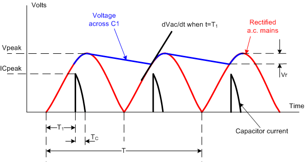
This picture is for full wave diodes and a big capacitor.
A battery is much like a capacitor.
The black trace at the bottom is the battery (capacitor) current you are measuring. (pulses, AC current) (AC in that it is not DC)
dIkNs.gif

You meter was built for sign wave current and its averaging will not be right.
Example you might have 10A pk and 1A average but the meter reads (?).
OR You meter might do really good averaging and read 1A. ???
 
Sure that's what the engineer 'said' but did he say anything about needing to use nothing less than the standard Nth level hyper-smart charger with intrinsic anti discombobulation monitoring? If not he's clearly not 'a real battery engineer'. :rolleyes:

Hi,

Yeah i had a battery that was combobulating and using the discombobulation switch on the charger cleared it right up :)

Congrats to Clarkdale for success with the second test.
I could not find any good data on the meter except that the frequency response is 50 to 60Hz, which of course means AC.

If you have the 200 amp AC model a trick to get it to read like the 20 amp model is to use a small coil of 10 turns of the wire or if testing AC appliances make up a plug in adapter with a coil with 10 turns of wire and clamp those ten turns all at once. The meter will read approximately 200 amps for a 20 amp real life AC current.
 
Last edited:
If you have the 200 amp AC model a trick to get it to read like the 20 amp model is to use a small coil of 10 turns of the wire or if testing AC appliances make up a plug in adapter with a coil with 10 turns of wire and clamp those ten turns all at once. The meter will read approximately 200 amps for a 20 amp real life AC current.

Works well!.

I've even done that mod to an old dial type watthour meter to make it a higher resolution unit. One was a 200 amp I converted to 20 amp so it now read 1/10th's of a KWH on last digit. Pretty handy for doing grid tie inverter fine tuning.

Another was going to be a 100:1 mod but I lost the guts to it before I finished it. :oops:
 
DC Hall meters are more expensive with degausing pods and DC drift adjust.

AC current readings measure peak AC currents then assume sine wave and convert peak to RMS by reducing peak by 30% or. so. VP = VRMS × √2

In the puzzle of your load test, you can try to measure current on battery + to charger and when load draws from battery current it also draws from charger, thus it reduces what is available to go to charge the battery, Perhaps that explains your connection readings.

unfortunately your readings are crude at best.
Better method is called a 50mV Kelvin shunt... basically a short piece of heavy wire with a DC drop of 50mV at full scale current. Then you use Vdc in mV scale to measure current.


Hi there Tony,

Just curios, what did you disagree with in post #17 ?
That's one thing i dont like about the 'disagree' button: we dont know what was disagreed with unless the user tells us.
 
Status
Not open for further replies.

Latest threads

New Articles From Microcontroller Tips

Back
Top