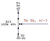
How I limit the current in the op-amp, I have no idea, Using a resistor as if it was a transistor, between Voltage source and collector.
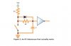
Sorry, I do not have in mind how the preset has to be. If it is a negative DC voltage a capacitor can stop it?
What does a series resistor do between the output and the input to the PIC.
Thanks a lot for the comment!
Sorry, I do not have in mind how the preset has to be. If it is a negative DC voltage a capacitor can stop it?
What does a series resistor do between the output and the input to the PIC.
Thanks a lot for the comment!