Continue to Site

Welcome to our site!

Electro Tech is an online community (with over 170,000 members) who enjoy talking about and building electronic circuits, projects and gadgets. To participate you need to register. Registration is free. Click here to register now.

  • Welcome to our site! Electro Tech is an online community (with over 170,000 members) who enjoy talking about and building electronic circuits, projects and gadgets. To participate you need to register. Registration is free. Click here to register now.

Changing voltage swing to Rail to Rail

Status
Not open for further replies.

alhoop

Member
I have a H11AA1 opto coupler that outputs 5 volts (VCC) with no input and 3 volts with a signal in. I want to use one transistor to change the swing from 5 volts to < 0.5 volts.
I know I can do it with a comparator but is it possible with a single trnsistor?
Thanks
Al
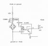
PS Forget my question above. Here are the circuits. The one on the left is used for train detection and I have over a dozen on my layout that work perfectly.
The one on the right is supposed to work the same but is very dependent on the type of DIP bridge rectifier used.
A VM18 works - a B40C800DM and a EDI-PL10 don't work. Seems there is not enough voltage drop
across the two latter bridges to fully turn on the H11AA1.
 

Attachments

  • marklin1.jpg
    marklin1.jpg
    95.3 KB · Views: 534
Last edited:
Why don't you just increase the resistance of the pullup resistor on the collector of the photo-transistor?
 
Last edited:
I agree with Mike. The transistor collector resistor is apparently too small.

According to the data sheet, the maximum "ON" transistor current is about 20% of the LED current you are applying to the coupler. So adjust the collector resistance accordingly.
 
I'll bump this back up - maybe it'll save some one else some time. I know I spent
a day on it before I decided to change the Bridge rectifier.
BTW the turnon voltage for the H11AA1 is 0.95 volts to 1.1 volts temperature dependent.
I measured 1.2 volts across the VM18 bridge and 0.95 volts across the B40C800DM
which supports my supposition above. Not a very stable design.
Al
 
Last edited:
The emitters in the opto-coupler are LEDS, and as such, are CURRENT operated devices, not VOLTAGE operated. For normal operation, the CURRENT through the LED should be ~10mA. The forward voltage drop is 1.2 to 1.5V. When you put an appropriate current limiting resistor (one that drops at least 2 to 3V so the current remains more-or-less constant) and add that 2V to the 1.2V to the forward drop across the LED means that you need an minimum voltage of ~3.2V.

What is the role of the "shorted" bridge rectifier? Are you trying to develop enough voltage across the two diode drops to operate the opto-isolator emitter? If so, that is not the way to build a "current sensor".
 
The emitters in the opto-coupler are LEDS, and as such, are CURRENT operated devices, not VOLTAGE operated. For normal operation, the CURRENT through the LED should be ~10mA. The forward voltage drop is 1.2 to 1.5V. When you put an appropriate current limiting resistor (one that drops at least 2 to 3V so the current remains more-or-less constant) and add that 2V to the 1.2V to the forward drop across the LED means that you need an minimum voltage of ~3.2V.
The emitters may be current operated but if you don't apply ~1 volt they won't operate at all - see the spec sheet.

What is the role of the "shorted" bridge rectifier? Are you trying to develop enough voltage across the two diode drops to operate the opto-isolator emitter? If so, that is not the way to build a "current sensor".
That is exactly the role of the short from + to - . And it works for me in at least 15 circuits. Suggest you see N-Scale Magazine May-June 1993 page 54.
Al
 

Attachments

  • h11aa1.jpg
    h11aa1.jpg
    43.8 KB · Views: 245
Last edited:
...
That is exactly the role of the short from + to - . And it works for me in at least 15 circuits. Suggest you see N-Scale Magazine May-June 1993 page 54.
Al

It is a very marginal design, which is WHAT YOU ARE COMPLAING ABOUT!
 
I can see using the bridge rectifyer for train detection, But I dont see a use for the one on the right. Just power the opto from the 5 volts using a dropping resistor and forget the bridge rectifyer. Andy
 
Not complaining now.
This works fine with any of the bridge rectifiers.
Gives 1.8 volts across the bridge/back-to-back diodes
and 40 ma through the H11AA1, two thirds of the max rating.
 

Attachments

  • test1.jpg
    test1.jpg
    66.8 KB · Views: 213
Whats it for?
Fair question. I want to be able to sense with a microcontroller when there is no voltage between the two rails either positive to negative or negative to positive.
It is about the only way to sense externally when a Marklin Z-Scale transfer table has reached a track position.
 
OK than glad it works.Thare may be an easyier way with op amps but hay as long as it works for you. Andy
 
Status
Not open for further replies.

Latest threads

New Articles From Microcontroller Tips

Back
Top