mading2018
Member
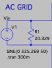
So what I understand so far, if I want to have 16 A out from a voltage source (230 V RMS) which is 325.269 V in amplitude (peak), can I simply add an resistor in parallel to achieve that?
R = 325.269 V / 16 A = 20.329 ohm
Do you think guys if I am on the right track? So if I am want simply to have another current from the voltage source, I just change the resistor to a different value?
R = 325.269 V / 16 A = 20.329 ohm
Do you think guys if I am on the right track? So if I am want simply to have another current from the voltage source, I just change the resistor to a different value?
Attachments
Last edited:
