Electro Tech is an online community (with over 170,000 members) who enjoy talking about and building electronic circuits, projects and gadgets. To participate you need to register. Registration is free. Click here to register now.
Welcome to our site! Electro Tech is an online community (with over 170,000 members) who enjoy talking about and building electronic circuits, projects and gadgets. To participate you need to register. Registration is free. Click here to register now.
Hi,
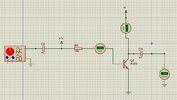
I am trying to amplify the ac input signal but any input value results in 0V output, Can anyone what's wrong with my circuit? I don't want to use a voltage divider bias configuration.
The first thing I was taught about biasing a transistor is to never simply use one base resistor to a supply voltage.
Because each transistor has a different current gain and has a different base-emitter voltage even if they have the same part number.
Also, the current gain increases as the transistor heats up.
Therefore a voltage divider biases the base plus an emitter resistor is added to 0V.
Sometimes a biasing resistor is connecting between the collector and base for negative feedback.
Comment 1: "Different base-emitter voltage"? A transistor does not "have" such a voltage. The base-emitter voltage Vbe is applied externally - and it has a certain relationship to the emitter resp. collector current as defined by the well known exponential formula (which, however, is remarkably temperature sensitive).
Comment 2: From the last sentence one could get the impression that such a resistor between C and B should/could be used in addition to an emitter resistor. No, this is not recommended - this would be counter productive.
It is the emitter resistor which provides negative feedback and, thus, stabilizes the device against the temperature influence as mentioned in my comment 1 above.
There is one disadvantage of the shown bias scheme if compared with the Re method (emitter resistor):
The input resistance is reduced (Miller effect) whereas RE will increase the input resistance.
For this reason, I think that the Re-feedback is the preferred method for stabilizing the Q-point,
Yes, although the input impedance is likely dominated by the low Rbe of a grounded-emitter amp (in the neighborhood of a few kΩ, depending upon the emitter current).
Interesting, the distortion of a grounded emitter amp due to the non-linear input current versus input voltage, can be reduced if the base drive is a high-impedance (constant-current) source, such as from the collector of a common-emitter input stage.
This site uses cookies to help personalise content, tailor your experience and to keep you logged in if you register.
By continuing to use this site, you are consenting to our use of cookies.